![]()
The CMS PIX Phase I upgrade CO2 cooling: a full scale prototype ready for tests
Low temperature cooling systems using evaporative Carbon Dioxide (CO2) have been used for particle detectors since 2000 by the Silicon Tracker of the AMS02 experiment at the ISS (International Space Station) and for the VELO vertex detector of the LHCb experiment at CERN.
As a refrigerant, CO2 features environmentally friendly physical properties, as it is non-flammable, non-toxic and it has a much lower Global Warming Potential than any other refrigerant on the market. In HEP detector applications such characteristics are attractively coupled with the radiation hardness and the excellent thermo-fluid dynamic properties, which allow a significant reduction in the material budget allocated to the on-detector cooling structures. Because of all these advantages and based on the excellent performance of the two existing systems, the vertex and tracking detectors of the next generation are starting to use evaporative CO2 cooling for thermal management.
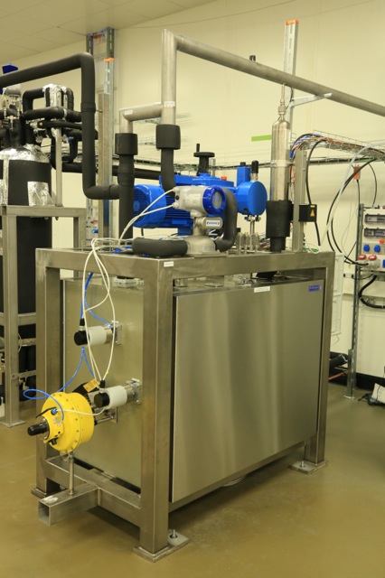
Figure 1: TIF Cooling Plant
A new pixel detector has been designed for CMS (Phase I Pixel Upgrade), in order to preserve the high tracking quality at luminosity and pile-up beyond the original specifications. It features four layers in the barrel (one more than the present detector) and three disks in the end caps (also one more than the present detector) and it will provide an additional fourth space-point measurement over the whole tracking pseudo-rapidity range. New readout electronics will allow the pixels to operate at the highest foreseen luminosity without data loss. The new CO2 cooling system combined with a modified cabling scheme and new lightweight mechanics will contribute greatly to the material budget reduction in the tracking acceptance.
The new detector will be put in operation during an extended technical stop in winter 2016/2017. Given the very short time available for the connection of the new detector to all services, CMS has requested the cooling system to be installed and commissioned during LS1. The demanded performances aim for 15 kW of cooling power at -20 C evaporation temperature, an unmatched size for an evaporative CO2 system of a HEP detector. It requires careful design in order to scale the successful layout of the LHCb VELO cooling system.
Aiming to fully validate the cooling system scheme and experimentally confirm the thermal design of the detector components before assembly, CMS has decided to build a full-scale prototype of the cooling plant, before freezing the design for P5. The cooling team of PH-DT has been mandated for the design, construction and commissioning of both the prototype and the final system.
The full-scale prototype is now at the end of the commissioning phase in the CMS Tracker Integration Facility (TIF) at CERN. It meets the full detector cooling power requirements (15 kW) and it is the largest one ever built using a CO2 pumped two-phase principle.
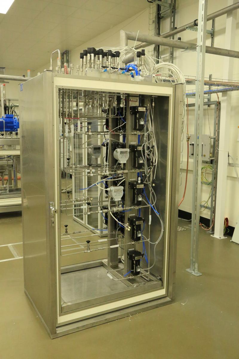
Figure 2: TIF manifold
An integrated approach has been adopted during the design phase, putting together a team of PH-DT and CMX experts. The design of the cooling plant is strictly dependent on the achievable performance of the detector: for this reason, mock-ups of detector cooling loop have undergone an extensive testing program both at CERN and in other CMS Pixel institutes. The thermo-dynamic performance of preliminary designed detector loops is first calculated through an ad-hoc developed simulation tool, implementing the latest empirical models of two-phase flow development published by Prof. Thome of EPFL, and then tested on laboratory CO2 cooling systems. The parameters of flow and pressure drops in single loops and parallel loops have been verified in the most demanding detector operating conditions, i.e. at room temperature during commissioning and at the lowest temperature for end-of-life irradiation level, leading to the correct sizing of the plant capacity.
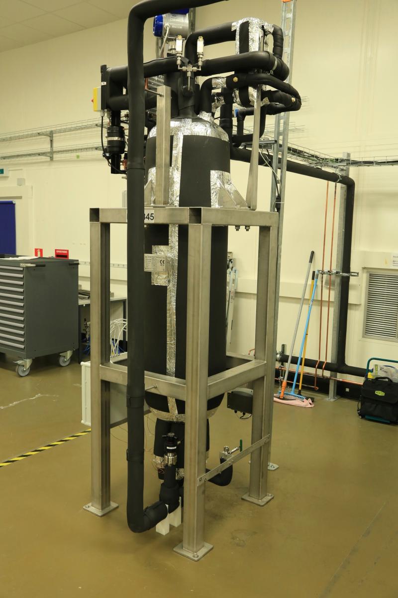
Figure 3: TIF accumulator
With such data, the cooling plant has been designed to match the full detector requirements. Intensive work has been put in selecting the most appropriate components, respecting the technical specification of 110 bar service pressure and a -40 C operation temperature (the minimum reachable by the existing primary system). For the manifold components, the additional requirements of radiation resistance and magnetic field tolerance have been added, since the final manifold of the CMS Pixel CO2 cooling system will sit in the experimental cavern.
Once the design and procurement phase completed, the workshop of the PH-DT group, responsible for the construction of the detector’s gas systems since many years, has been in charge for the construction. Considerable effort has been put on the quality control of the production, with visual and x-ray inspection of welds and fine tuning of the welding procedures up to the final version, which will be used for the production of the P5 cooling systems as well, according to the standards required by the European Pressure Equipment Directive.
Once installed at the TIF, the cooling plant and the manifold have been connected by means of co-axial transfer lines, where the liquid feeding the manifold runs in the inlet pipe, whilst the gas and liquid mixture returning to the plant continues its evaporation in the outlet pipe, maintaining the liquid line in sub-cooled state. The two pipes have been insulated by means of a vacuum jacket.
The process control systems have been developed thanks to the joint efforts of the PH-DT gas and cooling crews. The general layout implemented, common to gas systems and other CO2 cooling systems designed in the PH-DT gorup, is based on a Schneider Programmable Logic Controller (PLC) for the process control, and a user interface based on WinCC OA SCADA system. The control software conforms to the UNICOS CPC6 (Unified Industrial Control System Continuous Process Control) framework of CERN. PLCs are placed on the CERN Technical Network physically detached from the outside world for security reasons. The MODBUS protocol is used for the communication between the SCADA server, which is located in the CERN Control Center (CCC), and the PLCs.
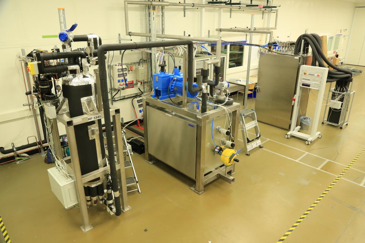
Figure 4: TIF overview
The commissioning process at TIF has started with the electrical and control connections checkout, followed by the validation of system sub-assemblies: the accumulator, the pump, etc.
The operation covers low and high flows and temperatures, allowing a careful margin for further request of the detector, connecting the plant to an ad-hoc dummy load: this has improved the overall performance and pushed the single components to their operation limits, acknowledging for the discovery of a few non-conformities on some of them. In addition, the transfer lines between the cooling plant and the manifold have been tested in operation and their design has been validated for the installation in the CMS underground premises with the final plant and manifolds.
Today, the cooling system's general layout has been validated, as well as 95% of the components, and the purchases for the P5 system can start. At P5, the reliability requirements and the wish for different operating temperatures in different sub-detectors during the commissioning phase have led to a double folded design for the final cooling systems. In the final configuration, two cooling plants, each one capable of the full cooling power, as the TIF one, will be built and will feed two independent manifolds (one for the Forward detector, the other for the Barrel). In case of failure of one of the two cooling plants, the other can be connected to the second manifold and operate both sub-detectors at the same time.
The fine-tuning of the TIF cooling system will continue in the next months, up to the connection of the first detector full-scale mock-up.
REFERENCES
- Verlaat B. , Controlling a Two-Phase CO2 Loop Using a Two-Phase Accumulator, ICR07-B2-1565, International Conference of Refrigeration, Beijing, China, 2007
- John R. Thome et al., New prediction methods for CO2 evaporation inside tubes: Part I – A two-phase flow pattern map and a flow pattern based phenomenological model for two-phase flow frictional pressure drops, International Journal of Heat and Mass Transfer, Volume 51, Issues 1–2, January 2008, Pages 111-124, ISSN 0017-9310
- John R. Thome, New prediction methods for CO2 evaporation inside tubes: Part II—An updated general flow boiling heat transfer model based on flow patterns, International Journal of Heat and Mass Transfer, Volume 51, Issues 1–2, January 2008, Pages 125-135, ISSN 0017-9310
- J. Daguin, J. Noite, P. Petagna, H. Postema, P. Tropea, B. Verlaat, “Evaporative CO2 cooling system for the upgrade of the CMS Pixel detector at CERN”, 10th IIR-Gustav Lorentzen Conference on Natural Working Fluids 2012 (GL2012), Delft, pp. 1066-74
- L. Zwalinski, J. Daguin, J. Godlewski, J Noite, M. Ostrega, S. Pavis, P. Petagna, P. Tropea “ The control system for the CO2 cooling plants for physics experiments”, in preparation for 14th International Conference on Accelerator & Large Experimental Physics Control Systems, October 2013, San Francisco (USA)