![]()
The ATLAS High Granularity Timing Detector
Introduction
Given the challenging conditions posed by the HL-LHC, ATLAS is currently in the process of constructing a novel precision-timing silicon detector, the High-Granularity Timing Detector (HGTD), which provides a time resolution of 30 to 50 ps for charged particles [ATLAS-TDR-31]. The detector covers a pseudorapidity range of 2.4 < |η| < 4 and comprises two double-sided Low Gain Avalanche Detector (LGAD) silicon layers on each side of ATLAS, covering a total active area of 6.4 m².
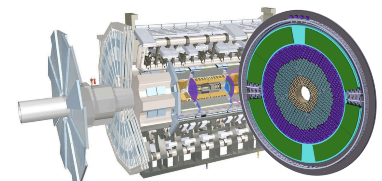
The precise timing information is used to disentangle pileup interactions in the same bunch crossing, complementing the excellent spatial resolution of the upgraded ATLAS Inner Tracker (ITk). With a timing resolution six times smaller than the temporal longitudinal spread of the beam spot, tracks in collisions occurring very close in space, but well-separated in time, can be distinguished. The layout of the HGTD is shown in Figure 1.
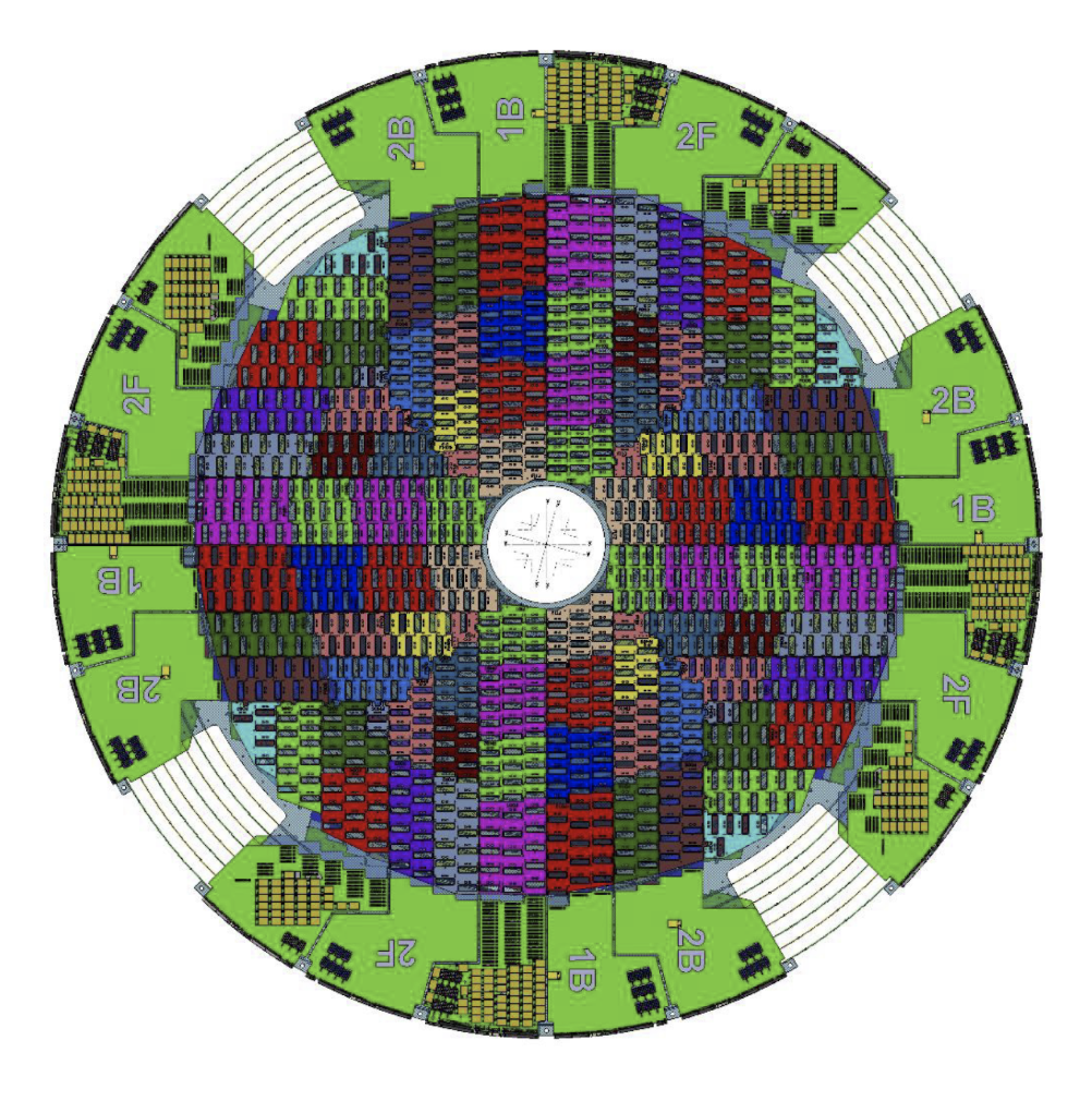
Figure 1. Layout of the HGTD. The placement of modules and the Peripheral Electronics Boards (PEBs) are shown. The active LGAD coverage is from 2.4 < |η| < 4.
The individual LGAD pads have a 1.3 × 1.3 mm2 pitch and are located on a sensor of 15 × 15 total pads. Sensors are bump bonded to readout ASICs, referred to as ALTIROC, to make a hybrid. Two hybrids are glued to a module flex to assemble a module. In total, HGTD comprises over 8000 modules each containing 550 individual readout pads, for a total of 3.6 million channels.
The ALTIROC ASIC provides both Time-of-Arrival (TOA) and Time-over-Threshold values for precise timing determination. The ASIC also contains a dedicated readout path for high-precision luminosity measurements based on 40 MHz hit counting, supporting both online and offline luminosity determination throughout the HL-LHC. The community is involved in an extensive testing of the pre-production modules in both test beam and test bench measurements. It is vital to qualify the full performance of pre-production modules, including ensuring the time resolution criteria are met.
Figure 2 shows measurements of the time resolution of a hybrid assembly with a pre-production ASIC (ALTIROC-A) and pre-production sensor, demonstrating a per-hit time resolution of 42 ps, well within specifications. The time resolution is defined as the sigma of the Double-Sided-Crystal-Ball fit on the distribution of the TOA differences between the hybrid and a reference MCP-PMT detector, with a time resolution of 10 ps.
The TOA of the hybrid is evaluated as the TOA given by the ALTIROC Time-to-Digital-Converter multiplied by the value of the Least Significant Bit (LSB). The chip is calibrated to an LSB of 20 ps. The TOA of the MCP-PMT is evaluated with the CFD-50% method and corrected by the phase of the internal 40 MHz clock of the chip. The measurements of hybrids and modules are performed both at SPS and DESY II test beam facilities, as well as with a Sr-90 setup at CERN.
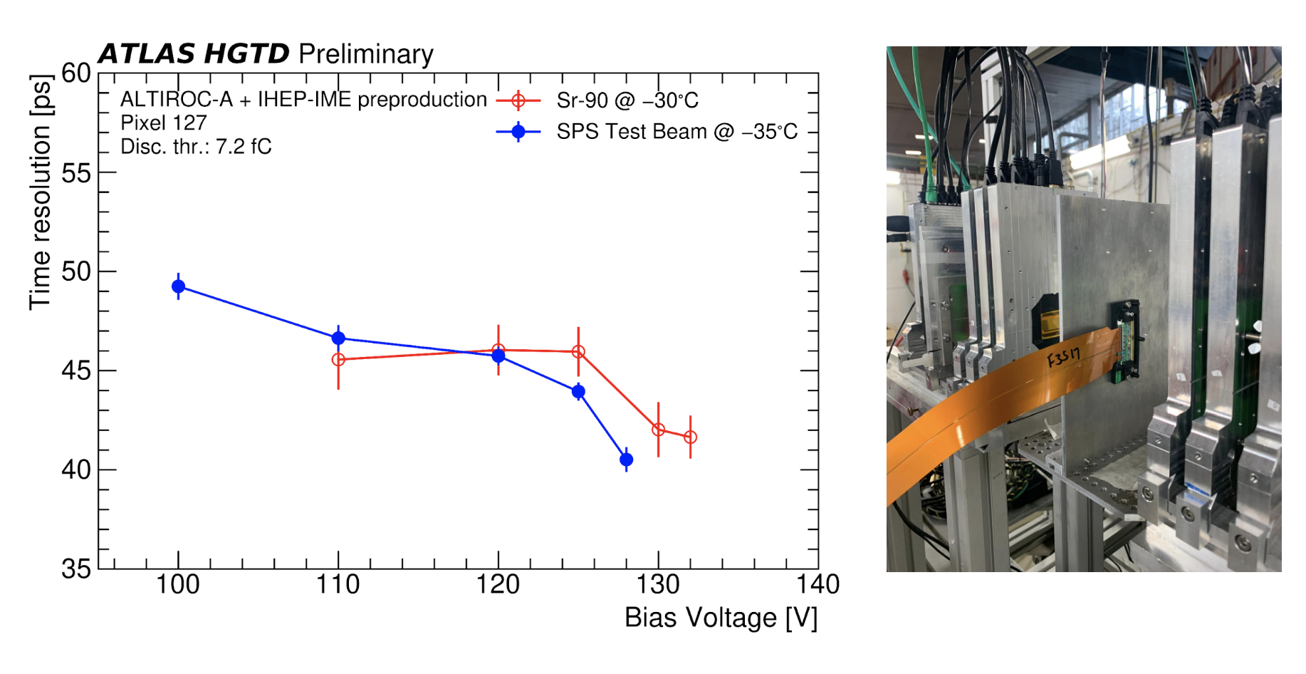
Figure 2 (left): Time resolution for different voltages of a hybrid assembly with an ALTIROC-A front-end chip and a pre-production sensor, measured in the April 2025 test beam at SPS (120 GeV pions) and a Sr-90 setup. (Right): HGTD module tested at DESY II, connected to readout through flex tail.
Modules are then loaded on Detector Units (DUs). There are 48 different DU types which are repeated across the detector, covering both front and back sides of the cooling plate. Four of these DUs have been assembled using prototype modules to be tested at the Demonstrator at CERN.
The HGTD demonstrator setup is located inside the HGTD cleanroom and reproduces a slice of the HGTD detector with its complete readout chain. It consists of a prototype PEB type 1F connected on one side to 54 prototype modules via flex tails and on the other side to the FELIX, High Voltage, Low Voltage, and Interlock systems placed in racks outside the cleanroom (see Figure 3). The 54 prototype modules are equipped with prototype LGAD sensors, bump- and wire-bonded to ALTIROC2 (27 modules) and ALTIROC3 (27 modules) ASICs. The entire setup is housed in a Faraday cage and connected to a mobile CO₂ cooling plant. Several tests have already been performed, validating the full readout chain with the current prototype components.
Figure 3: Demonstrator setup showing the PEB 1F (green board on the left), the flex tails (orange), and the modules (not visible, as they are located behind the flex tails). The PEB is connected to the HV system via HV pigtails (thin blue cables) and HV cables (red), to the LV system (black cable), and to the interlock (thick blue cable). The modules and PEB are mounted on a cooling plate connected to the CO₂ system. The entire setup is enclosed in a Faraday cage (the metal box covered with Cu sheets). The black cables behind the demonstrator provide dry air.
The final HGTD detector assembly and demonstrator testing are carried out inside the ISO Class 7 ATLAS HGTD cleanroom in Building 180 (see Figure 4). The cleanroom is both temperature- and humidity-controlled and equipped with connections to external CO₂ cooling plants, which provide evaporative cooling for module tests at the operational temperature of –30°C. Dry air (dew point –60°C) is also available to ensure ultra-dry conditions during cold tests. A mobile CO₂ cooling plant with a maximum cooling capacity of 1 kW is currently used for tests of the HGTD demonstrator. Cold tests of the final detector will be performed using an extension of the 10 kW Babydemo cooling plant, located about 50 m from the HGTD cleanroom in Building 180.
The racks containing the Low Voltage, High Voltage, Interlock, DCS, and DAQ systems are installed outside the cleanroom and connected to the detector inside via cables and optical fibers through cleanroom feedthroughs (see Figure 4).

Figure 4 (left): HGTD cleanroom overview: on the left-hand side, the vessel stand is visible; at the center, the demonstrator box; and on the right-hand side, the working table for detector component reception tests. Dry cabinets for storing HGTD components are also present. (Right): Racks for the demonstrator located outside the cleanroom: from left to right, Rack 1 hosts the HV system, Rack 2 hosts the FELIX, DCS, and Interlock systems, and Rack 3 hosts the LV system.
The HGTD cleanroom also hosts a probe station for LGAD sensor testing. The probe station is placed inside a tent to guarantee ISO 6 cleanliness level. Production testing is currently being ramped up successfully and is shown in Figure 5.

Figure 5: Probe station for the LGAD sensors testing inside a tent to ensure ISO class 6.
Two main tools will be used for the assembly of the final detector, which will take place in the HGTD cleanroom; they are shown in Figure 6:
- Half-Disk assembly stand – serves as a support for the instrumented Half-Disk and its associated services. It allows all necessary manipulations during instrumentation and testing, as well as safe transfer of the instrumented Half-Disk to the vessel.
- Vessel stand – holds the two hermetic vessel packages in a vertical position, including their external moderators, fire-retardant shielding, and the dummy calorimeter front wall. It also serves as a platform for the CO₂ Babydemo manifold box and associated services required for the final tests. The stand is currently being finalised in the clean room.

Figure 6 (left): Prototype assembly stand. (Right): Prototype vessel stand inside the cleanroom: the dummy calorimeter front wall is mounted on one side of the stand.
Summary
The High Granularity Timing Detector, a silicon timing detector as part of the phase-2 upgrade of ATLAS, is into the production phase. Extensive testing is on-going to validate the performance of the detector, including a full 54 module demonstrator. The community is also preparing for the integration phase in the HGTD cleanroom with extensive work having been done to prepare for the arrival of the production components.