![]()
The ATLAS Inner Tracker Integration at CERN
Introduction
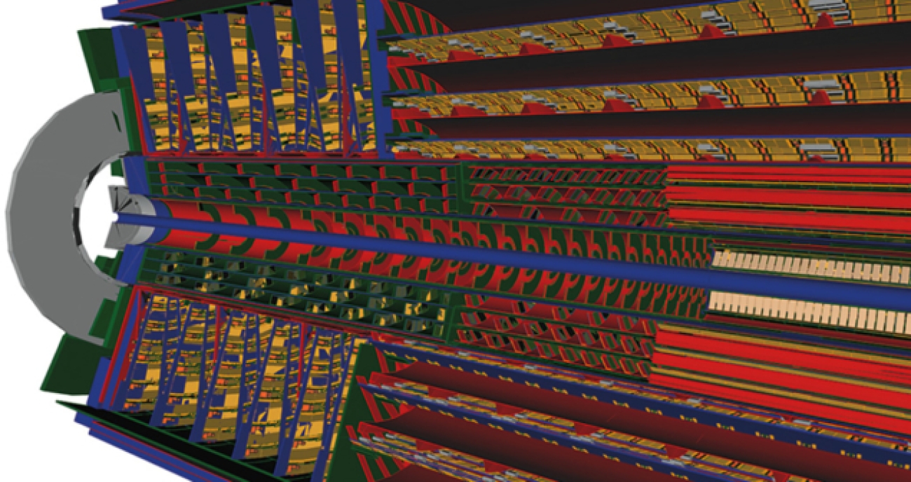
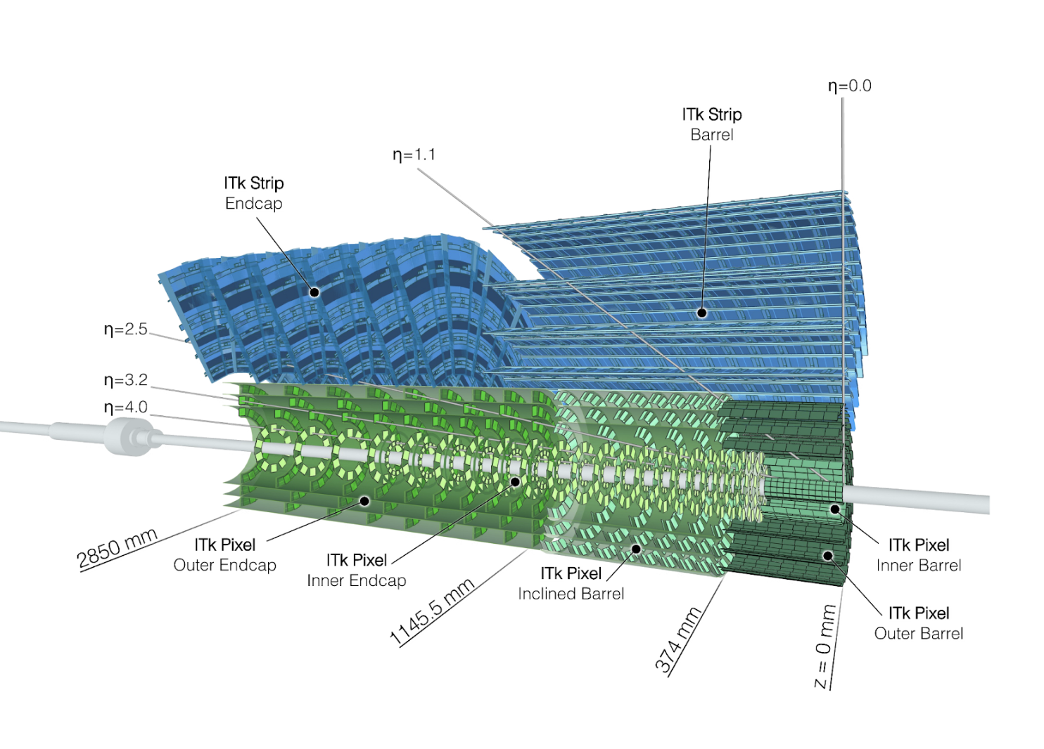
The ATLAS ITk (Inner TracKer) is a new all-silicon tracker that will replace the existing ATLAS Inner Detector (ID) to meet the requirements imposed by the high-radiation and high-hit occupancy environments of the HL-LHC (High-Luminosity LHC). The ITk consists of multiple layers of silicon detectors arranged into Barrel (cylindrical) and End-cap sections, providing hermetic coverage around the collision point. The innermost part is the Pixel system, comprising ~13 m² of pixelated silicon and ~5 billion readout channels. Surrounding the Pixel layers is the Strips system, comprising 165 m² of strip-implanted silicon with 60 million readout channels. A section of the ITk detector is shown in Figure 1.
The ITk collaboration is currently constructing the different parts of ITk which will be assembled in a cleanroom at CERN prior to installation in the experiment during LS3. This article provides an overview of the activities at the CERN SR1 cleanroom, which serves as the surface integration facility for the ITk at Point 1. Activities are currently focusing on installing the global mechanics, preparing the infrastructure for the integration work on pixels and strips, and receiving the first detector parts. Integration tests have already started using individual detector segments.
The construction of the ITk is a worldwide endeavour with teams in 22 countries contributing to this effort. The production is distributed all over the world and requires technical as well as logistic challenges to be mastered. The ITk is planned to be fully assembled on the surface in SR1 by Spring 2029, ready for lowering into the cavern and insertion into the ATLAS experiment.
The Assembly Site
The CERN SR1 cleanroom at Point 1 was the central assembly site for the ATLAS Inner Detector in 2004-2007, and will now serve as the main integration facility for the ITk Strips and Pixels detectors. The facility has been expanded to accommodate the integration of the various ITk sub-detectors, including an additional 250 square meters of space. Additionally, a radiation lab facility has been integrated to conduct system tests to support the development of ITk DAQ and DCS during the integration process.
Significant infrastructure developments have been necessary to facilitate the integration activities for both Strips and Pixels. These include two major cooling plants: a CO2 plant to provide the evaporative cooling needs of the integrated detectors (down to -35 °C), and a monophase (C6F14) plant to provide cooling (at typically 17 °C) for electronics and the reception testing of detector parts. High-flow dry air (dew point: -80 °C) is in place to ensure ultra-dry conditions during cold tests. The Class-100,000 cleanroom environment is controlled for temperature and humidity, while the presence of high-voltage, welding, cooling, and pressure test activities require strict safety protocols.
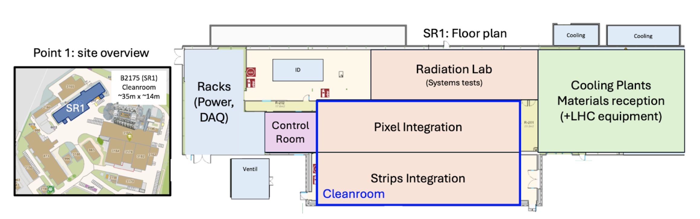
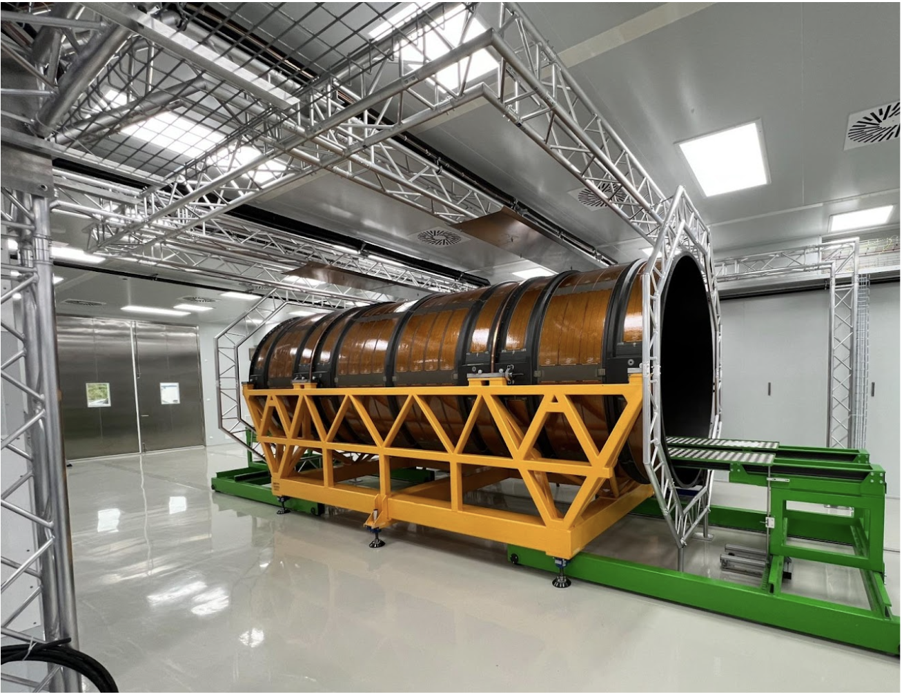
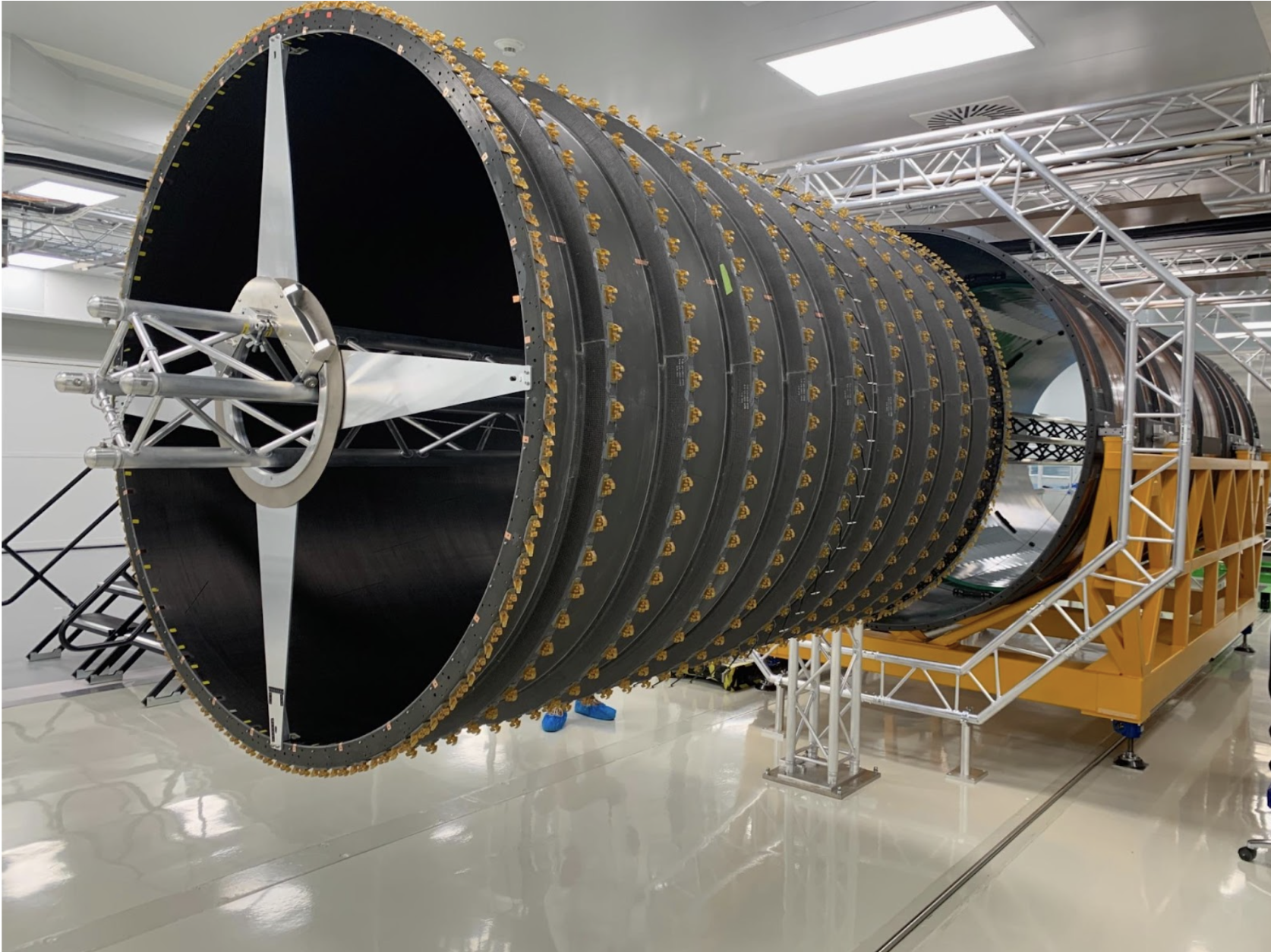
Given that the Strips and Pixel detectors are integrated independently and follow distinct assembly procedures, their integration activities are carried out in separate areas of the SR1 cleanroom. Both detector systems will ultimately be inserted into and fully enclosed by a ~6-meter-long, 2-meter-diameter carbon structure known as the Outer Cylinder (OC), which defines the outer envelope of the ITk detector. To support the ongoing integration of the Strips detectors, the OC has already been installed in the Strips integration area, as shown in Figure 3.
To support integration activities, additional, detector-specific services and infrastructure have been installed, including bespoke platforms, support structures, insertion tooling, up to 16km of cabling for detector powering, fibres for readout, power supply crates and HV/LV cards, patch panels, interlocks for safe powering and cooling, Detector Safety Systems and environmental monitoring.
Strip Integration
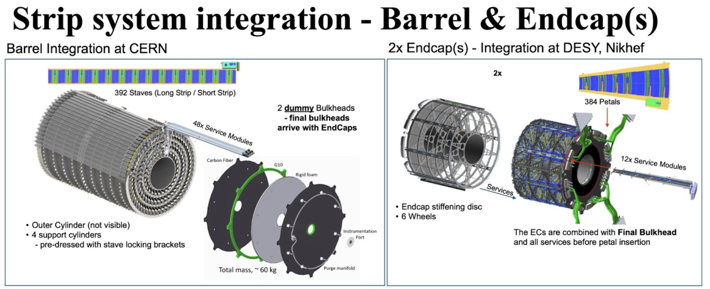
Strips integration is carried out at three independent sites: the Barrel section in SR1 at CERN and the two End-cap sections at DESY and NIKHEF. Upon their completion, each End-cap will be transported to SR1. The Barrel section comprises four carbon cylinders supporting 392 Staves, connected via 48 Service Modules, while each End-cap comprises 6 disks supporting 192 petals connected via 12 Service Modules. After the Barrel is completed, the End-caps are inserted into each end of the OC which then completes the ITk Strips detector.
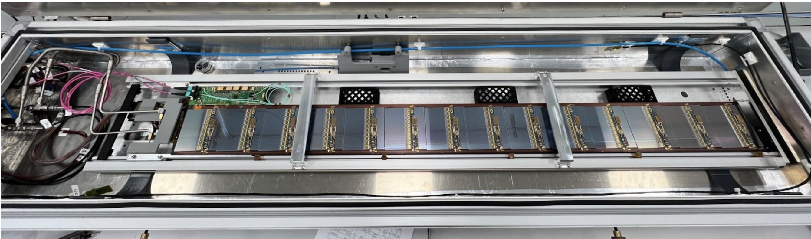
Staves will be delivered to SR1 in batches over a period of ~2 years. Upon arrival, each stave will be inspected, then cooled, powered, and electrically tested to ensure that its electrical characteristics still match the data taken at the stave construction sites. Figure 5 shows a test stave within its test box at one of the two stave reception setups in SR1.
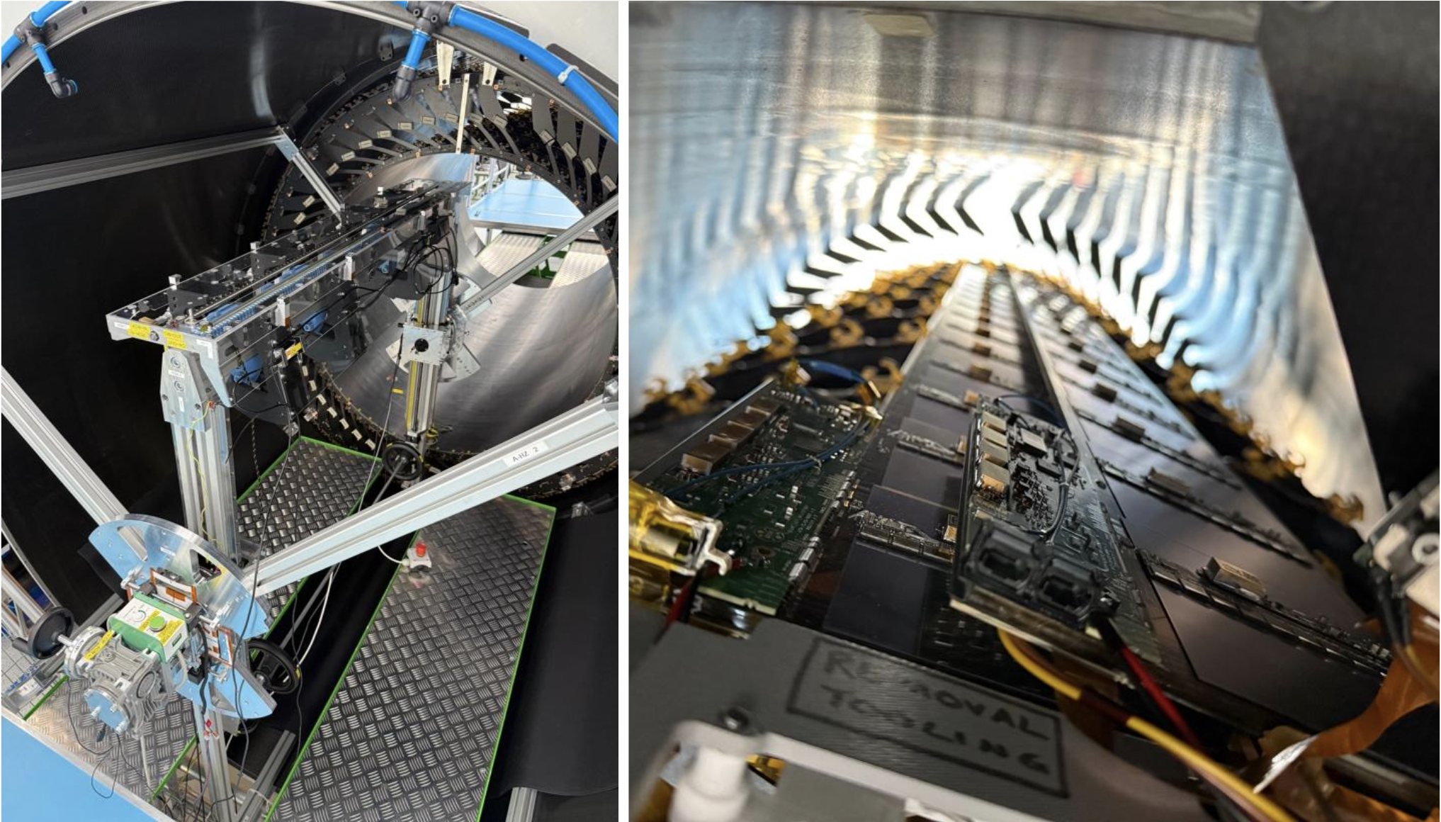
Tested staves are then stored in a dry environment, ready for insertion onto one of four support cylinders. The first two cylinders have already been inserted into the OC and fixed in place, as shown in Figure 6.
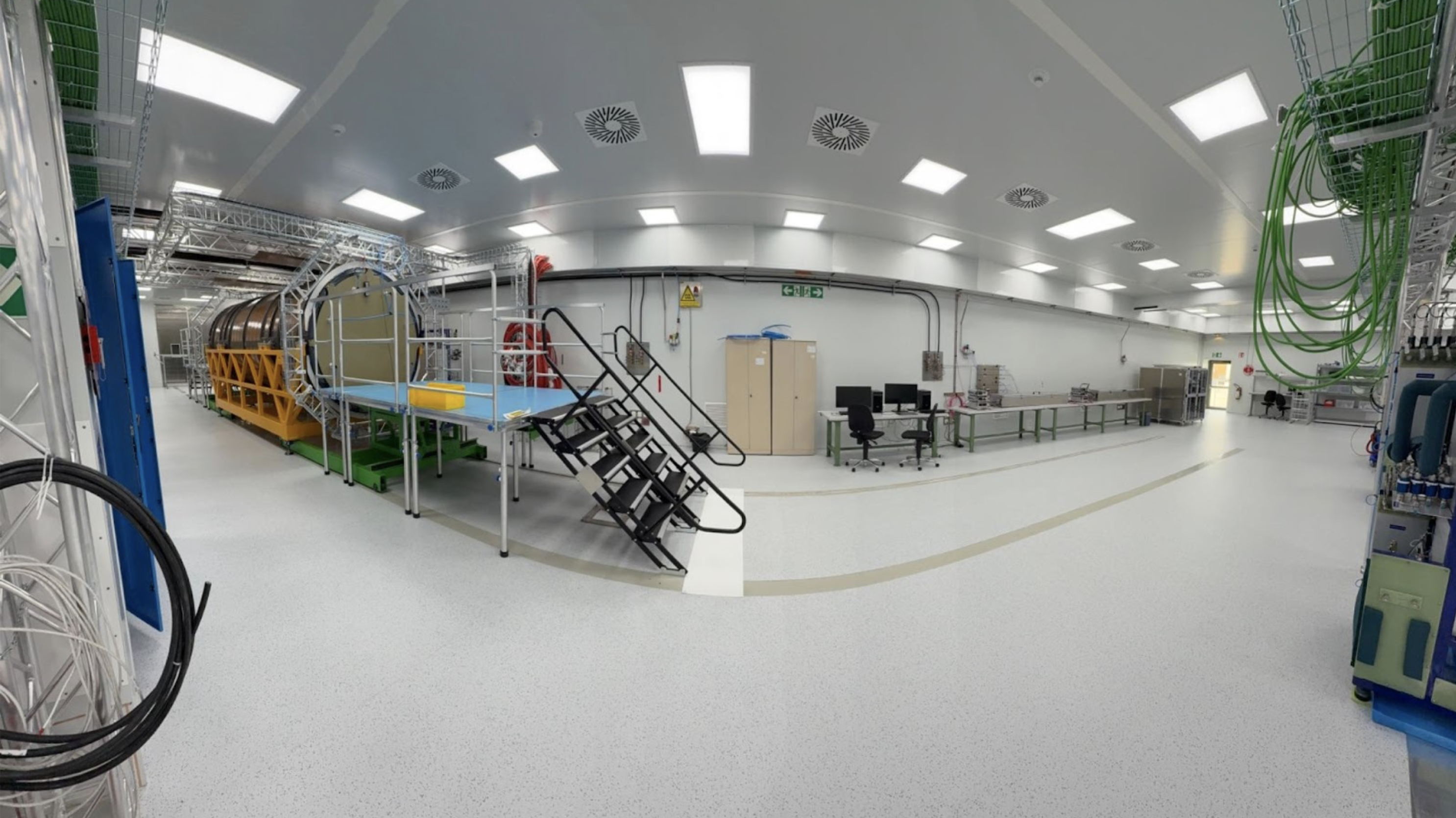
A panoramic view of the Strips integration area is presented in Figure 8, showing the Outer Cylinder (OC), the surrounding work platforms, and part of the installed cabling infrastructure. In order to provide power and readout the strips (up to 48 staves), the ATLAS technical coordination team installed almost 19 km of cables between the cleanroom and the rack area.
| Strips | # of Layers | # of Detectors | Surface [m²] | Channels [M] | Strip Pitch [µm] | Strip Length [mm] |
|---|---|---|---|---|---|---|
| Barrel | 4 | 392 Staves | 104.86 | 37.85 | 75.5 | 24.1 - 48.2 |
| Endcap | 6 | 384 Petals | 60.4 | 22.02 | 69 - 85 | 19 - 60 |
| Total | 776 | 165.25 | 59.87 M |
Pixel Integration
The pixel detector is built in four segments. These include the two inner layers, known as the Inner System, which is partially constructed in the US and subsequently finalized in SR1. The central three outer layers, referred to as the Outer Barrel, is built at CERN by various funding agencies. The two Outer Endcaps are manufactured in Italy and the UK. The Outer Barrel and the Outer Endcaps are integrated into the Outer System in SR1, before they and then the Inner System are inserted into the Strip system.
An overview of the key numbers is given in the table below.
| Pixels | # of Layers | # of Modules | Surface [m²] |
|---|---|---|---|
| Inner System | 2 | 1556 | 2.39 |
| Outer Barrel | 3 | 4472 | 6.93 |
| Outer Endcaps | 3 | 2344 | 3.67 |
The integration of the pixel detector is taking place in a dedicated area in SR1. Its preparation has been ongoing for several months. The detector construction activities include the reception of Outer Barrel components, which will take place in the so-called radiation lab in SR1. The integration of the services and detector layers of the Outer Barrel will be conducted in the main clean room, located opposite the strip detector integration area. The Outer Endcaps and Inner System detector segments are assembled outside of CERN and will undergo a reception test after their arrival in SR1. This is foreseen to take place in the area next to the Outer Barrel integration area in the main cleanroom. The proximity will facilitate the assembly of the Outer System and then its relocation to the Strip integration area for insertion.
Not only will the assembly of the detector take place in SR1, but also testing and quality control. Both electrical tests, which require cooling of the detector segments and parts of the test equipment, as well as metrology and envelope control tests, will be conducted. The preparations in the main cleanroom are progressing well. Fig. 9 shows installed power distribution racks and off-detector cables and fibres. The racks act as patch panels between equipment and cables for powering, interlock and control, and readout in the rack room to the detector test setups. The ATLAS technical coordination team supported the cable installation, and the pixel teams have already verified the mapping. More test equipment, like power supplies, PCs, and interlock units, is expected to arrive in the coming months. They will then be commissioned sequentially.
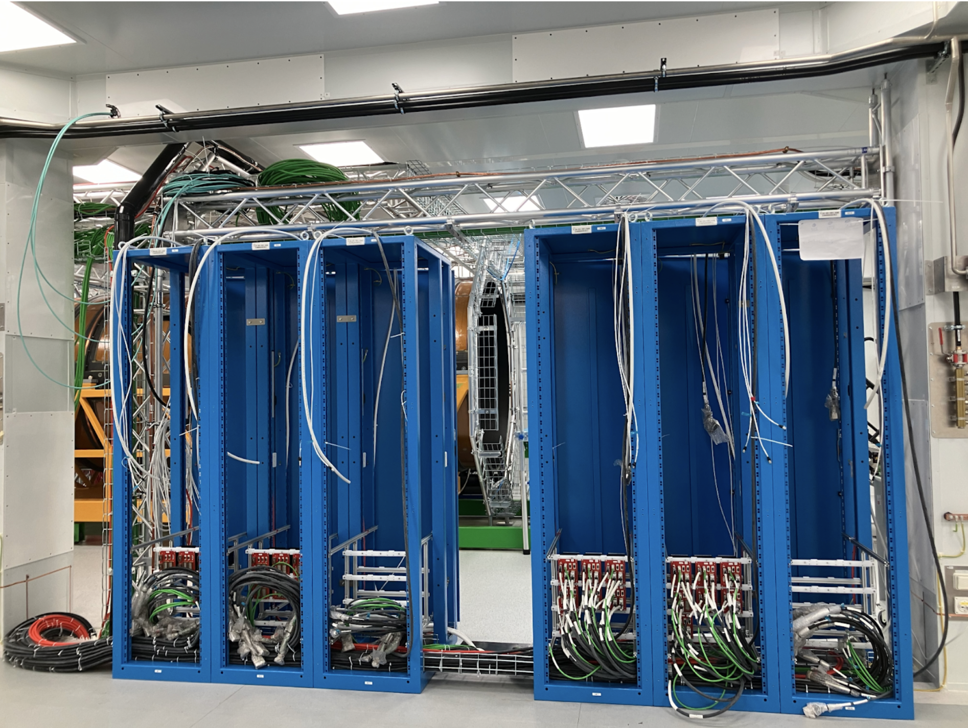
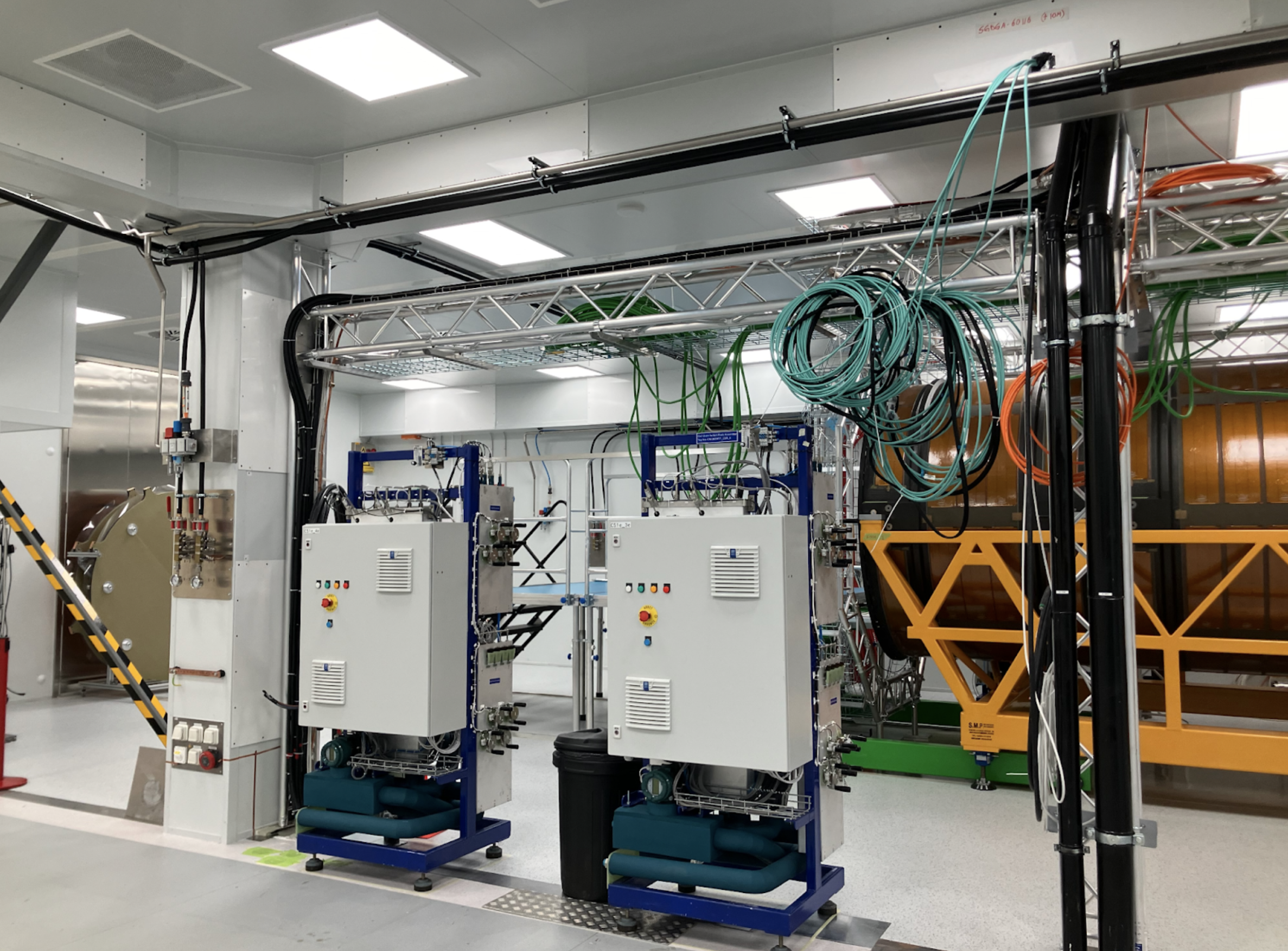
Fig. 10 presents an image of two out of the five CO2 cooling racks that have been installed in the pixel areas. The detector segments under test require cooling to be provided, as will be done during normal operations with CO2. The ATLAS cooling team has already installed the required units, and their commissioning is in preparation.
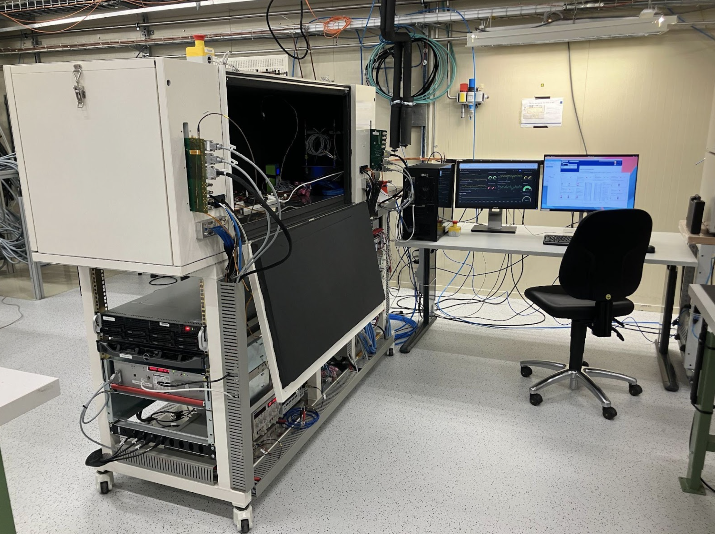
The first test setup for pixel integration was recently installed in the radiation lab. This laboratory is located next to the main cleanroom and will also allow for the staging of local supports after their arrival from the six production sites. The setup will be used for the reception test of the loaded local supports of the Outer Barrel. A photo of the setup, which utilises both CO2 and monophasic cooling, can be seen in Fig. 11. The electrical equipment, including power supplies, optoboxes, and finite state machine, is in commissioning.
Additional equipment is expected to arrive in SR1 in the coming months, and the pixel team is preparing for its installation and commissioning. They are also working on mapping and connectivity, as well as handling tests to ensure they are well prepared when detector segments arrive in SR1. A review of the site readiness is anticipated for the end of 2025.
Summary
The ITk integration area in the SR1 cleanroom is being fully equipped for the integration of ITk. The Strip integration is progressing well and is expected to start integrating the barrel staves in the summer of 2025. The pixel integration is commissioning the equipment for quality control tests of several setups, designing and producing integration tools and preparing the test procedures. The parts from various institutes for pixel integration are foreseen to arrive from the beginning of next year. The SR1 integration area has undergone extensive work over the past few years and is now ready for integrating the ITk.