![]()
CMS pixel upgrade: a truly global endeavor
A new and upgraded pixel detector has just been installed in the heart of CMS in this extended year end technical stop (EYETS 2016-17), marking the end of a five year long construction project. The CMS pixel detector that was replaced was performing very well. However, the upgrade was necessitated mainly by operational limits that would restrict the ability of CMS to profit fully from the anticipated LHC luminosity increases in the coming years.
Overview
The new detector was delivered to CMS in six main pieces (Figs. 1 and 2 ): four end-cap (FPIX) half-cylinders, with three half-disks each, all pre-assembled at Fermi National Accelerator Laboratory (FNAL) from modules made in the US; two barrel pixel (BPIX) halves, assembled at Paul Scherrer Institute (PSI), with modules made by several European consortia.
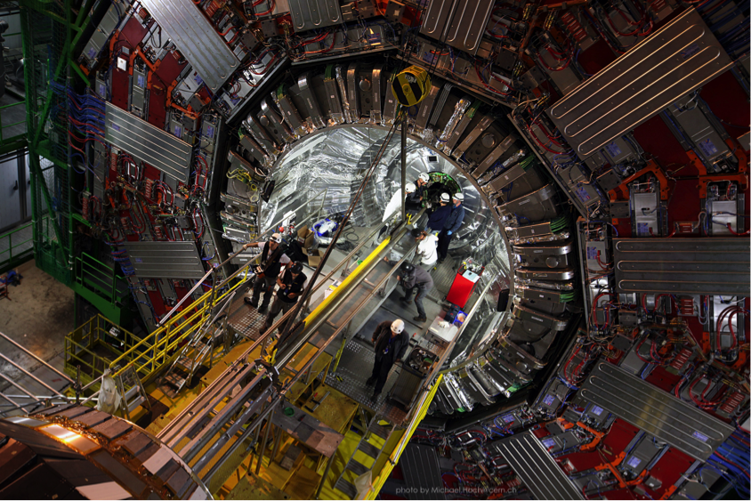
Fig.1: Schematic of the CMS pixel detector with four FPIX half-cylinders (in blue), which are inserted inside the service cylinders of the 2 BPIX halves (in grey). The whole assembly is about 5.6 m in length and 40 cm diameter when inserted into the CMS Tracker. The active pixel detector volume spans a 1.1 m long central section.
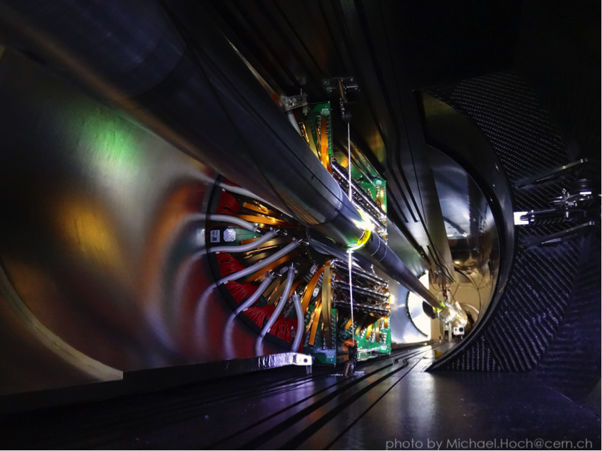
Fig 2: BPIX and FPIX assembly at PSI and CERN respectively. Key features here include the very lightweight mechanical supports and very fine CO2 cooling tubes and the impressive amount of cabling to be managed in such a tight volume.
All of these pixel detector sub-assemblies were installed very smoothly into the centre of the CMS Tracker (Figs. 3 and 4), by BPIX and FPIX insertion teams, following well practiced procedures. Very careful attention was paid to the mechanical clearances to the beam pipe, which remained in place throughout the operation as well as the alignment of both the beam pipe and detector to the nominal beam-line.
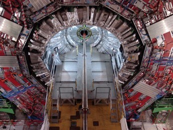
Fig. 3: CMS in the open configuration ready for pixel installation on Feb 20. The pixel detector is fitted into the ~15cm gap around the beam pipe and the surrounded silicon microstrip tracker detector.
Fig. 4: Insertion of one of the four FPIX half-cylinders
The upgraded pixel detector has one more layer of modules in both barrel and forward regions (Fig. 5), with a total of 123 million pixels, up from 66 million previously. The extra layer will provide greater robustness in the tracking, vertexing, and b-quark tagging performance. The pixel system seeds the overall track-finding pattern recognition steps, and it is also used in stand-alone pixel-only tracking mode as an essential part of the high-level trigger, which is selecting the events that CMS stores for later analysis.
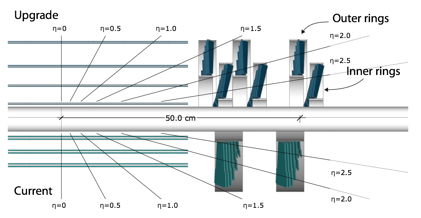
Fig. 5: Comparison of the original and upgraded pixel detector geometries. Top half shows the upgraded detector, and the bottom half the previous detector.
The pixels are individually 100 x 150 microns in size, with 66560 pixels per silicon sensor, matched with pixelated readout chips (ROCs) that amplify and store signals from charged particles passing through the sensors. 16 ROCs bump-bonded onto each sensor in a 2 x 8 format make up a ‘bare-module’. A dedicated printed circuit board HDI (high-density interconnect) is glued and wire-bonded to each bare module, providing the power, clock, trigger and control connections, as well as the output data links for the ROCs.
A key part of the upgrade has been the evolution of the design of the ROC, which was done by the PSI group, as for the original detector. The increasing luminosity was generating increasing inefficiencies in the original pixel ROCs, particularly in the modules nearest the beam-line where the hit-rate is the greatest. The upgraded ROCs include more buffering and a new readout mechanism for the data that reduces greatly the inefficiency. Much of the front-end electronic readout chain was also modified, along with the back-end data-acquisition system (DAQ), in order to accommodate the much higher data rates anticipated over the lifetime of the new detector up to LS3. Hit rates in BPIX Layer 1 are expected to approach 600 MHz/cm2, compounded by the effect of Layer 1 now being 15 mm closer to the collision point than in the original detector. This repositioning was done to profit from the possibility to improve the vertexing and b-tagging performance, following the installation in LS1 of a central beampipe with smaller diameter, 45 mm reduced from 60 mm.
Despite adding an extra tracking layer to the overall detector layout, reduction of the mass inside the tracking volume has been another key objective of the upgrade, again with the goal of improving the overall quality of tracking and vertexing. Much lighter mechanical supports have been used and the service electronics has been mounted further away from the collision point, just outside of the active tracking volume. There is as well a substantial reduction in the amount of material for detector cooling, following a switch from fluorocarbon monophase cooling to an evaporative CO2 cooling system. Bi-phase CO2 cooling is much more efficient in removing heat, allowing the use of smaller volumes of coolant and therefore much smaller cooling tubes on the detector.
CERN EP in the pixel upgrade
The CERN EP department has made a number of important contributions to the pixel upgrade project. CERN staff working with Helsinki and National Taiwan University groups built 250 BPIX modules, with support from EP detector technology group (EP-DT) who carried out wire-bonding of the modules in the Departmental Silicon Facility in Building 186. The EP-DT group, working with EP-CMX group, and CMS Technical Coordination, built and installed the largest CO2 evaporative cooling system for an experiment to date, with 15kW capacity for -25 °C operation. The cooling plants and transfer lines for the CO2 to/from the detector were installed already in LS1 to profit from the full opening of the CMS barrel wheels to allow the vacuum-insulated CO2 pipe installation, and to profit from the following two years to gain a great deal of operational experience ahead of the final detector installation.
Another important, enabling ingredient for the pixel upgrade has been the use of DC-DC converters to bring power to the detector. The converter boards, made by the RWTH Aachen University group, are based on the FEAST chip, which was designed and validated for radiation environments by the EP-ESE group. With DC-DC conversion, we are able to transfer the larger power needed for the new larger detector, at a higher voltage, ~ 10 V, which means lower currents and therefore lower resistive power losses in the cables. The DC-DC solution was an absolutely necessity as we were constrained to re-use the existing electrical power cables to the detector, as these will not be replaceable until LS3. The previous power supplies were also re-used after some refurbishment, done quickly in parallel with the new detector installation.
The mechanical integration exercise, along with final installation and testing of new cooling manifolds and new pipes at the pixel detector bulkhead, along with optical fibres and electrical cables, was done by a CERN-based engineering team. The team included several CERN Technical Students, who enjoyed a very memorable work-experience in the project working underground on this open-heart surgery of CMS. Extensive 3-D CATIA modeling was done first for the pipes, cables and optical fibres, followed by prototyping of parts and trial installations on a full-scale mockup in building 187 at CERN. These careful advance preparations enabled very rapid replacement of all of the pixel detector services at point 5 (Fig. 5), which was essential to maintaining the very tight overall schedule for the detector replacement, and working very efficiently also minimized the radiation exposure of the personnel involved.
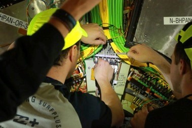
Fig. 6: Careful connection of the cooling lines at the detector bulkhead, following procedures practiced on a full scale mockup.
Off-detector, in the USC55 underground service cavern, the new pixel DAQ was installed in January and February. The main ingredients are 108 ‘front-end drivers’ (pixFEDs), and 19 ‘front-end controllers’, all based on the FC7 board developed by EP-ESE electronic systems group and Imperial College (Fig. 7). The pixFEDs each collects and process signals from 24 optical fibres from the detector, building up the event fragments, and transmitting them to the CMS central DAQ system over 10 Gbit/s links. The DAQ firmware development has been achieved through a collaboration of the Institut Pluridisciplinaire Hubert Curien Strasbourg (IPHC), Institute of High Energy Physics Vienna (HEPHY) groups, Kansas State University, Rice University, with support from experts in EP-ESE and EP-CMX. The project profited greatly not only from the FC7 development but also the qualification programme of microTCA crates and ancillary components (backplanes, controllers, power supplies) carried out by the EP-ESE group, and the earlier upgrade of the CMS trigger and clock distribution system (TCDS) by EP-ESE and EP-CMD groups.
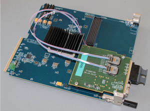
Fig. 7: PixelFED DAQ board based on the FC7 with a mezzanine including two 12-way single-mode optical receivers and a 10Gbit/s output link to the central DAQ.
For the project as a whole, we were able to gain a lot of early experience with a “pixel blade detector”, a small slice of the upgraded pixel detector with 8 prototype modules, half with DC-DC power, and the upgraded optical readout and control links. The pilot blade was installed inside the original FPIX during LS1 and was operated through 2016, first with the VME DAQ and then later with the microTCA DAQ, allowing us to focus well ahead of installation of the final detector on system integration issues, development of the operations procedures, field-testing of DAQ firmware, online software, as well as the modification of data quality monitoring tools.
In parallel with all the work going on to complete the detector and the associated hardware systems on time for the EYETS, there was also a large investment made to be ready on time with the software needed for 2017 Physics operations. Tracking and high level trigger experts in EP-CMG group worked with other CMS experts to update the high level trigger and tracking codes, and the CMS detector Monte Carlo simulations, fully integrating the upgraded pixel detector into the regular CMS workflows.
At P5, the pixel detector installation was completed on March 26th, and a full checkout of the services connections for the cooling, power, readout and control systems was made, before proceeding with the ‘cold checkout’, running the full detector at the 2017 operating temperature of -20 °C, before giving a green light for the closure of the CMS detector. All of these pixel checkout steps went well, with only relatively minor concerns, some of which were able to be quickly addressed, and CMS was closed according to plan, with 96% of the pixel detector operational, with the missing small fraction mainly suffering from connectivity problems that will be revisited at the next access, which if all goes well will be in 2019 during LS2.
Since the checkout, the detector has undergone a series of planned commissioning steps, with the detector control, readout, and DAQ systems all brought into coherent operation on the full-detector scale for the first time as fully integrated parts of the CMS experiment operation. Commissioning continued with the first collision runs in Week 21 going well with regards to the pixel detector operation. These early runs were dedicated to timing scans needed to make the adjustments to synchronise all of the pixel modules with respect to the incoming particles. Early data taking runs have been also dedicated to voltage scans for determining the appropriate working point of the silicon sensors, as well as runs for making the first spatial alignment measurements of all of the modules with collision tracks, which is combined with earlier data taken with cosmic rays.
In conclusion, this has been a complex, intense, and exciting construction project for many of us in EP and in CMS as a whole. The smoothness of the execution of the very complex installation, integration and checkout process reflected really well the effort and dedication of the many people at CERN and in the CMS collaboration involved in the project. Replacing a really important CMS sub-detector in a relatively short, even if specially extended winter stop, when CMS was running very smoothly just beforehand, was always going to be nerve-wracking at times. As things stand, the new pixel detector begins its operational life full of promise; and we look forward to stronger CMS Physics performance all the way up to LS3, and benefitting from all this recent experience from development through to commissioning and operations, which will add even more strength to the next phase of detector upgrades for HL-LHC.