![]()
The new CMS Timing and Control Distribution System
It is of paramount importance that all parts of an LHC experiment are synchronized to each other and to the passage of particles in the centre of the experiment. The original CMS Timing, Trigger, and Control (TTC) system made this possible during the first period of data-taking at the LHC from 2009 to 2012. Detector upgrades foreseen to be completed in the coming years require a greater number of individual detector partitions to be available than were available in the TTC system. This along with the upcoming upgrade of the CMS Global Trigger (GT) system allowed us to re-define the boundary between the previous TTC and GT systems and separate the pure trigger functionality from that of controlling and synchronizing the data-taking of CMS. The new CMS Timing and Control Distribution System (TCDS) has been designed, built and installed in CMS during the first Long Shutdown (LS1) of the LHC and is now routinely used to control CMS data-taking.
The CMS TCDS distributes timing and control (synchronization) data flowing to the detector front-ends and receives back status information related to the readiness of the detector systems to handle more triggers. In the downstream (towards the detector) direction, this means that the clock reference that is synchronous with the particles in the LHC accelerator is distributed along with the fast control information required in order to keep the data-taking in step across the various detector systems that make up CMS. The detector systems are able to provide basic status information (TTS) regarding their readiness for accepting more triggers by sending data back to the TCDS in the upstream direction.
Physics triggers are received from the GT (existing and upgraded) system by the Central Partition Manager (CPM) module. This is the controller responsible for orchestrating global all data-taking in CMS that involves multiple sub-detectors. The system clock (received from the LHC RF systems) is also received by the CPM for further distribution. Residing in the same µTCA crate are a number of Local Partition Managers (LPMs) that are able to orchestrate local data-taking for a particular sub-detector in CMS. Each LPM contains eight identical firmware blocks that translate the generic synchronization commands emitted by the Partition Manager (Central or Local) into the sub-detector specific commands that are understood by the detector front-ends. The final module in the chain (of which there is one per detector partition) is the Partition Interface (PI). The PI serves as a fan-out for downstream clock and data (TTC), and an intelligent OR-based fan-in for the status information (TTS) coming back upstream.
An important new feature of the TCDS system is that it enables existing systems that interfaced to the pre-LS1 TTC system to be connected along with upgrading systems that are based on the new common CMS readout module (AMC13). The latter provides a bi-directional optical interface in contrast to the legacy systems where the TTC data are optical while the TTS are electrical signals.
The CMS TCDS is based on the uTCA family of standards, using full size, double width AMC modules in a 12-slot uTCA shelf with a telecom backplane and redundant power modules. In the partition manager crate, the backplane is used to distribute clock and fast timing commands from the CPM to the LPMs as well. These data are relatively low speed, being a 40 MHz clock and 160 Mb/s data. The backplane is also used to transmit control data downstream for the synchronization of the new CMS luminosity data acquisition system (LumiDAQ), this time using high-speed serial links running at 5 Gb/s. High speed serial links operating at 5 Gb/s are also used to aggregate the TTS information and send it from the LPMs to the CPM. This is where the use of the uTCA architecture is a major benefit to the TCDS project.
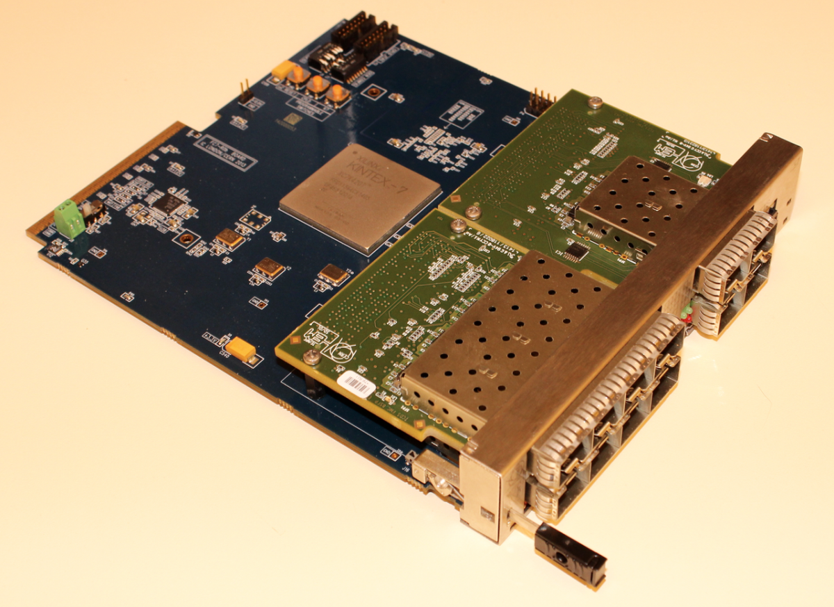
The CPM module reuses the same hardware as the AMC13 together with custom firmware. The LPM and PI modules are based upon the same base module, the FC7, and are differentiated by the choice of FMCs mounted on the FC7. A photograph of the PI is shown below.
The TCDS was installed in CMS in two phases: in the first phase a demonstrator was installed in parallel with the existing TTC system to allow sub-detectors to become familiar with the TCDS hardware and software functionality; and in the second phase the TTC system was removed and replaced with the full TCDS at which point CMS fully switched over to TCDS. Details of the rack, powering and monitoring provided for the TCDS system will be described. This was the first time a major system in CMS installed uTCA infrastructure and thus provided a model to be copied in subsequent installations, notably for the upgrades of the CMS Trigger systems.
The TCDS system was installed in CMS six months before the LHC restart in 2015. This time was used to commission the various systems and finalize the functionality required for data- taking with particle collisions in CMS. A particularly important part of the validation of the installation was the verification of the latency added to the existing system. This has been verified to be 2 bunch crossings more than expected during initial assessment. The main reason for this has been found to be the additional interfaces necessary for the transmission of the Physics Trigger between the TCDS and the existing GT.
The TCDS system represents the first major installation of uTCA hardware in CMS and as such provides a very useful reference for future applications of this technology in particle physics applications. We have successfully applied the uTCA architecture to the design, production, installation and operation of a timing distribution system for a major particle physics experiment.