![]()
Upgrading the ATLAS Level-1 Central Trigger
The ATLAS trigger system consists of a first-level trigger based on custom electronics and firmware, and a high-level software trigger (HLT) running on off-the-shelf hardware. The first level trigger (see Figure 1) uses information from calorimeters, muon and forward detectors which arrives at the bunch crossing rate of 40 MHz. This information is gathered by a set of components called the Level-1 Central Trigger (L1CT) in order to issue the Level-1 Accept signal (L1A) at a reduced rate (100 kHz). The detector front-end awaits the L1A to send out the buffered data, which will be further analyzed by HLT.
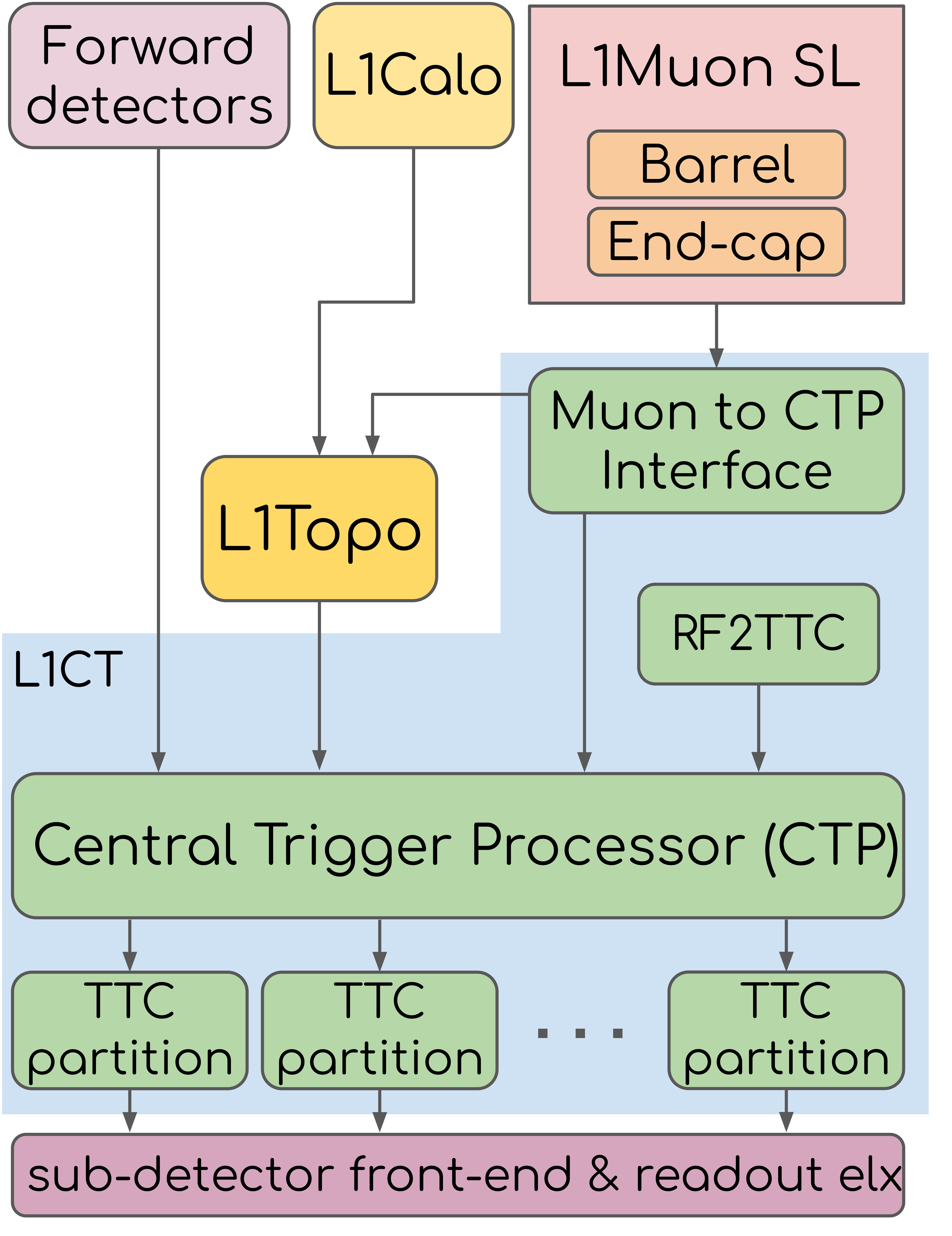
Figure 1: Simplified scheme of the ATLAS Level-1 Trigger architecture.
The main Phase-I hardware upgrade is the new Muon-to-CTP-interface (MUCTPI). The MUCTPI receives muon candidate information from the L1 Muon Sector Logic boards. The candidates are processed to avoid double counting due to geometrical overlap of chambers. Muon trigger object information is sent to the Topological Trigger Processor (L1Topo), which combines it with trigger objects from the calorimeters for event triggering based on multiple topological criteria. Finally, muon candidate multiplicities are sent to the Central Trigger Processor (CTP) to be combined with the information from forward detectors, calorimeters and L1Topo and to form the Level-1 accept decision.
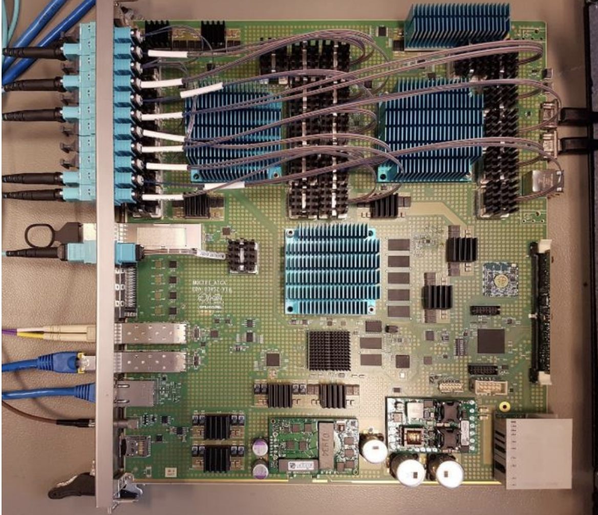
Figure 2: The new Muon-to-CTP-interface MUCTPI board.
The new MUCTPI receives more trigger candidates compared to its predecessor, with more detailed data using optical links instead of electrical ones. It improves the overlap handling by taking into account overlap between octants - previously not possible.
The new MUCTPI is built as a single ATCA blade using a number of FPGAs to implement the logic (the old MUCTPI system consisted of 18 VME boards!). A System-on-Chip (SoC) is used for control, configuration, and monitoring of the hardware. The SoC includes programmable logic which allows access to memories implemented in the processing FPGAs. The Processor System (PS) runs Centos Linux as an operating system. In addition, it configures and controls the hardware of the MUCTPI using standard interfaces. The run-control software is cross-compiled and deployed for ARM processor core architecture using automated CD/CI online tools, greatly improving the efficiency of the development lifecycle (implementation further described in IEEE proceedings document).
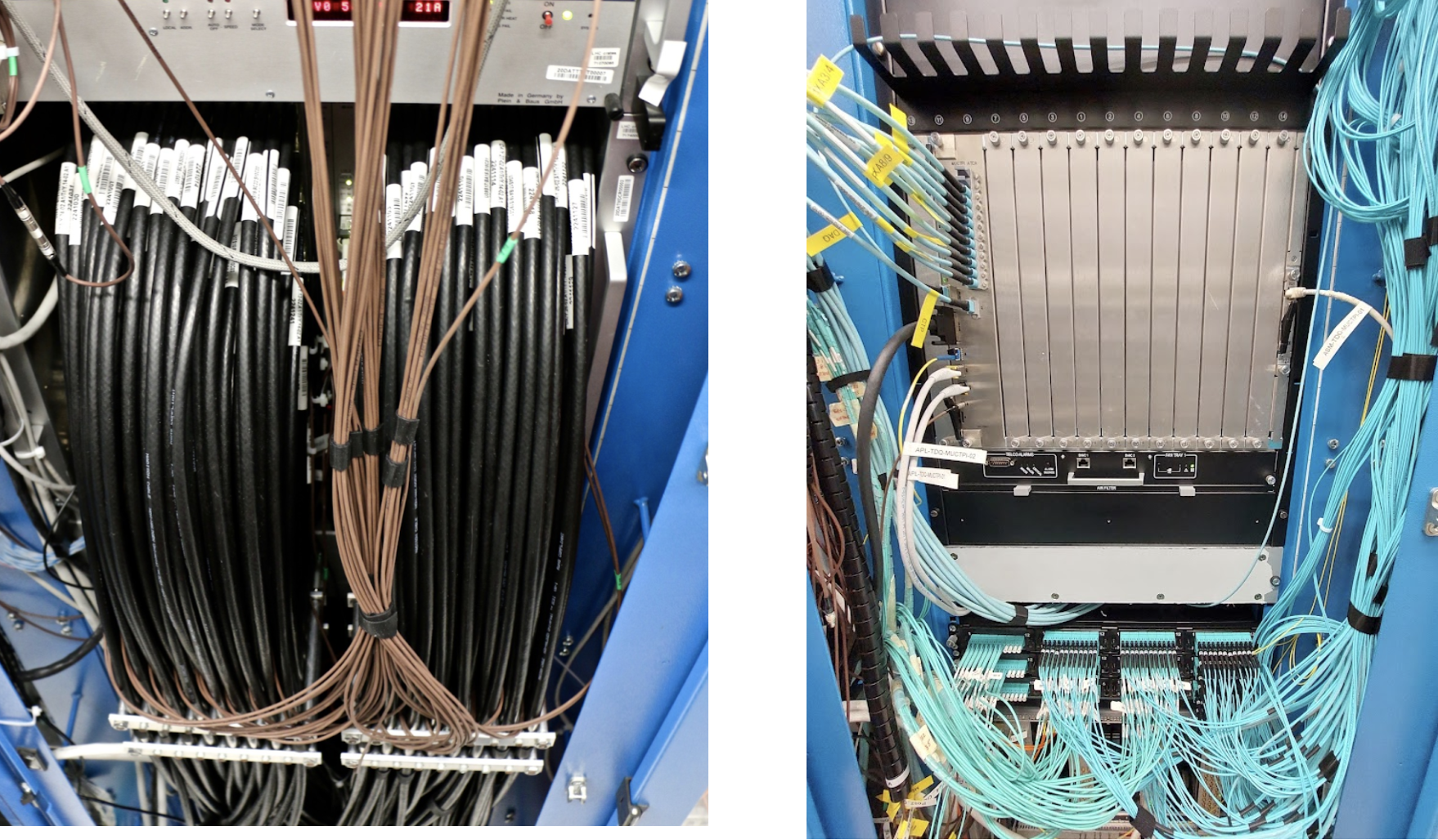
Figure 3: From copper cables to fiber optics: old versus new MUCTPI in the ATLAS cavern.
The MUCTPI was installed in the ATLAS counting room (USA15) in 2021. Physical connections to the interfacing systems were carried out. Namely, the input fibers from the Muon Sector Logic boards, the output fibers to the L1Topo and CTP, as well as other infrastructure items were connected and tested. During dedicated ATLAS testing periods additional integration tests were carried out together with the interfacing systems to validate communication and data flow. The MUCTPI commissioning was also presented at ICHEP and TWEPP during 2022 (read more in the corresponding proceedings).
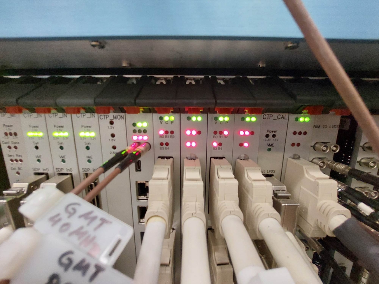
Already since LS1, a number of L1CT components have been updated. Namely, the CTP “CORE” and “OUT” modules were redesigned in firmware to accommodate direct optical inputs as well as a new configurable switch matrix which allows routing of all trigger inputs in a flexible way to form the trigger items. Furthermore, during LHC recommissioning there are a number of special runs (horizontal muons, beam splashes, VdM scans…) for which testing of the new ATLAS Trigger menu is needed. For all these cases, the Trigger menu undergoes complete testing and validation before each set of runs in order to verify validity of the look-up tables in the firmware.
Additionally, the distribution of Timing, Trigger and Control signals (TTC) is now largely carried out by a new VME card, the Atlas Local Trigger Interface (ALTI). It includes all the legacy functionality of the TTC family of boards, along with extra features. This upgrade was made necessary due to aging legacy electronics (20+ years old) which made them challenging to service and harder to find spares for.
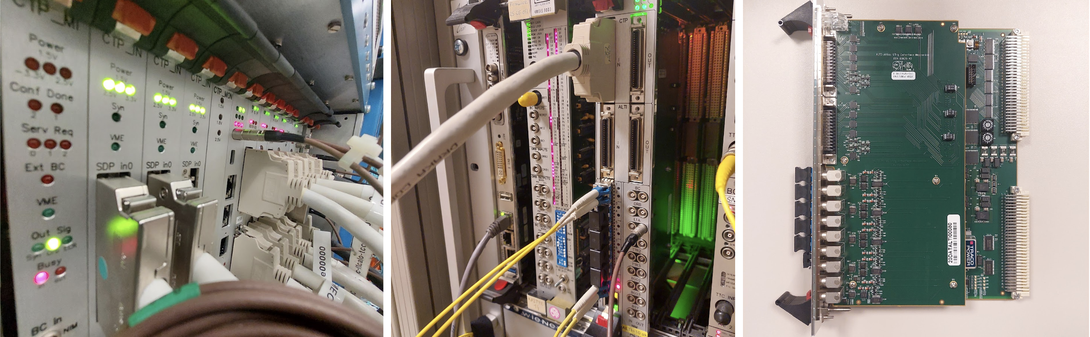
Figure 4: CTP (left) and ALTI (middle and right) boards in the lab.
All new hardware components are accompanied by the necessary updates to the code in Data Quality, Monte-Carlo simulation, offline reconstruction software, as well as new online control and test software to operate the new boards.
In closing, the ATLAS Level-1 Central Trigger is already in stable operation since the beginning of Run 3. After a number of upgrades during LS2 and as operation is more and more stable, the focus is widening to Phase-II upgrades with more exciting updates to come.
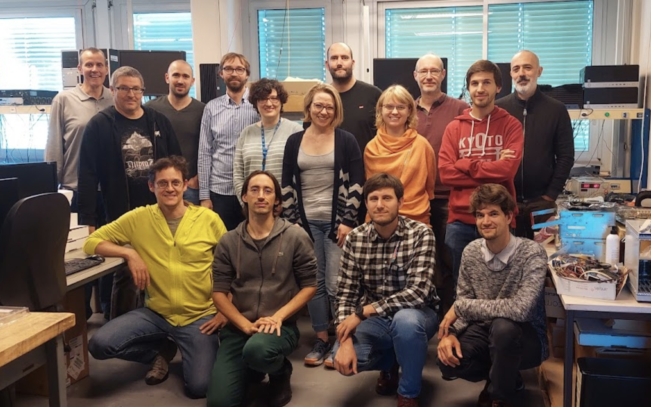
The L1CT work is a combined effort from members of EP-ESE-BE and EP-ADT-TR. The current L1CT team is: (top row, left to right) R. Spiwoks, S. Haas, Y. Afik, P. Czodrowski, R. Simoniello, S. Perrella, A. Marzin, A. Kulinska, T. Wengler, G. Muscarello, P. Vichoudis; (bottom row, left to right) T. Pauly, A. Koulouris, L. Sanfilippo, O. Penc; V. Ryjov (not in photo).