![]()
A safety and reliability perspective of the CERN RadiatiOn Monitoring Electronics (CROME).
CERN has the legal obligation to protect the public and the people working on its premises from any unjustified exposure to ionising radiation. In this context, radiation monitoring is one of the main tasks of the Radiation Protection Group. Currently, around 800 radiation detectors are permanently installed at various locations at CERN.
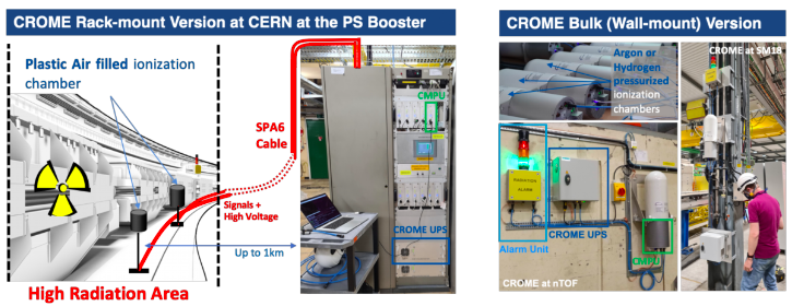
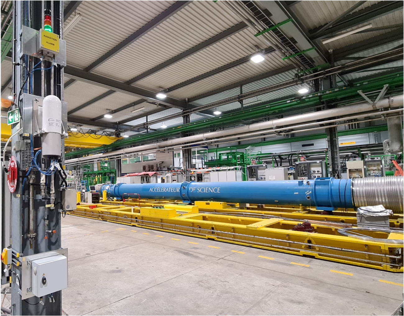
Figure 1. CROME System at CERN
Due to the stringent legislation in matters of radiation protection, the radiation monitoring systems must be able to measure very low radiation levels, pulsed radiation, monitor the ambient dose rate in real-time and generate radiation alarms and interlock signals based on measured levels and 150 configurable parameters (Boukabache et al. 2016). As one of the current monitoring systems has reached the end of its lifetime, the Radiation Protection group (RP) has developed a new system called CROME (acronym for CERN Radiation MOnitoring Electronics). As shown in Figure 1, CROME is composed of many sub-equipment available in two versions:
- A rack-mount version for areas with high radiation levels (Cf. Figure 1).
- A bulk version for areas with low radiation levels, which could be wall-mounted for fixed installations (Cf. Figure 1) or mobile as shown in Figure 2.
CROME has the ability of measuring very low dose rates down to 50 nSv h−1, whilst being able to measure radiation over a range extending over 9 decades without autoscaling. To reach these performances, the CROME Measurement and Processing Unit (CMPU) is based on the versatile architecture that includes new read-out electronics developed by the Instrumentation and Logistics (IL) section of the RP group coupled with a Zynq reconfigurable System on Chip (SoC) capable of performing complex processing calculations. CROME uses the FPGA section of the SoC for all safety critical functions (Toner et al. 2019).
The CMPUs are able to autonomously generate safety output signals that can be routed to physical alarm units and interlock systems. The states of these outputs are determined by the ambient equivalent radiation dose levels and a combination of run time configurable parameters.
The SoC's dual core ARM processors are running an embedded operating system which is used both for communication with REMUS (Radiation and Environment Monitoring Unified Supervision) supervisory system (Ledeul et al. 2018) and for data management.
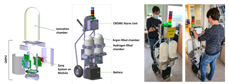
Figure 2. CROME Mobile version
Given the high expectations regarding the reliability of the monitoring system, its development process was supported by an extensive dependability study according to the IEC 61508 standard and its production has been almost entirely carried out at CERN, thanks to intra-departmental collaboration with TE, BE, EN and EP.
For the hardware integrity and functional verification of both the hardware and firmware, we have followed methodologies in accordance with the Safety Integrity Level (SIL) 2 as required by the IEC60532.
Hardware safety integrity is related to random hardware failures and comprises quantitative and qualitative requirements. Quantitative requirements include the calculation of the Probability of a Failure on Demand (PFD) or the Probability of a dangerous Failure per Hour (PFH) of the safety system. Qualitative requirements are related to the architectural constraints that limit the achievable Safety Integrity Level (SIL) based on Hardware Fault Tolerance (HFT) and the Safe Failure Fraction (SFF) of the sub-systems.
The verification methodology we followed for the CROME system comprises the following main steps:
Reliability Prediction: The first step of this approach is a reliability prediction for all components of the system. The failure rate of each component is estimated as Mean Time To Failure (MTTF) or Failures In Time (FIT) by either using standards (FIDES), field data or values from the manufacturer calculated through accelerated lifetime tests. These failure rates are the basis for all further calculations.
Failure Modes, Effects and Diagnostic Analysis (FMEDA): The second step is a Failure Modes, Effects and Diagnostic Analysis (FMEDA) where the necessary parameters λSD, λSU, λDD and λDU (safe detectable, safe undetectable, dangerous detectable and dangerous undetectable failure rate respectively), which are needed for the calculation of PFH and SFF, are determined. The FMEDA analysis was performed together with the board designers. Compared to standard FMEA, where all failure modes of each component, their immediate failure effects, failure effects at system level and failure causes are determined, a FMEDA does also include the failure mode probabilities and their diagnostic coverage. The failure rates come from the prediction and the failure mode probabilities can be obtained from standards or other databases. From the results of the FMEDA, the architectural constraints can be directly determined.
Fault Tree Analysis: The PFD or PFH can be calculated by using Fault Tree Analysis (FTA) based on the calculated failure rates λSD, λSU, λDD and λDU in the FMEDA. The calculation only takes the dangerous undetectable failures into account.
The results of the PFH and architectural constraints are then compared against the requirement tables of the standard and the achievable SIL can be determined. Considering both a PFH of 9.28 10-8 failures per millions of hours and a safe failure fraction of 97.4%, the hardware safety integrity of the CROME system conforms to SIL 2 (Hurst et al. 2020).
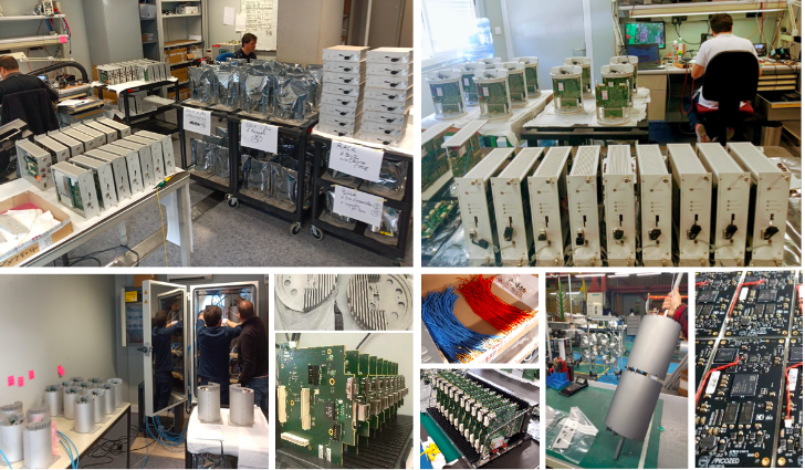
Figure 3. CROME Production at CERN
In order to be able to rely on the autonomous decisions regarding safety critical outputs, the functionality of the design must be systematically verified against its requirements. We perform functional verification according to our verification methodology in accordance with the IEC 61508 standard for safety-related programmable electronics. The 3 main pillars are:
Reviews: Design faults are very often caused by ambiguous requirements specifications or different interpretations by different persons. Reviews aim to overcome this problem. In order to validate the verification, we specify formal properties in natural language with a defined N:1 mapping between natural English and SystemVerilog. These statements are reviewed by the requirements engineers rather than the designers, which increases the independence between verification and design.
Formal Property Verification: We use SystemVerilog assertions that are fed into model checker tools that formally prove their validity on a design or output a counterexample. Proofs are valid for all possible input values (within the provided constraints). There is no need for specifying stimuli. This technique is very useful for bug-hunting. Several requirements concerning the safety-critical outputs could be formally proven.
Constrained-Random Simulation: The CROME system can be installed and used in many different environments. Therefore, many parameters of the system’s calculations can be configured at run time. It would be an extremely time-consuming task to specify input stimuli that cover all scenarios of interest with many different input values. Constrained-random simulation allows fast automatic generation of thousands of input stimuli. Only the verification scenarios need to be manually specified, which is done in terms of functional coverage statements.
All three methods contributed to finding safety-critical faults and increasing confidence in the system (Ceesay-Seitz et al. 2020).
As shown in Figure 3, CROME Production is ongoing as well as on-site installations. Currently, we have deployed 79 systems at PSB, PS, SPS, SM18 and the North-Area. Although, CROME development for LS2 is finished, a major update is expected for LS3 with the replacement of the current front-end with aCCURATE ASIC. This integrated solution is currently being designed in collaboration with EP-ESE-ME to extend the current measurement range to ]1fA -10uA]. The next milestone for CROME is the complete replacement of RAMSES system in both the LHC and the East Area with the installation of 400 radiation monitors of the new CROME system by the end of the LS3.
References
(Boukabache et al. 2016): Toward a Novel Modular Architecture for CERN Radiation Protection. Radiation Protection Dosimetry, Volume 173, Issue 1-3, April 2017, Pages 240–244, https://doi.org/10.1093/rpd/ncw308
(Ledeul et al. 2018): CERN Supervision, Control and Data Acquisition System for Radiation and Environmental Protection, In Proceeding of PCaPAC 2018, Hsinchu, Taiwan JACoWPublishing, doi: 10.18429/JACoW-PCaPAC2018-FRCC3
(Hurst et al. 2020): Overview of a Complete Hardware Safety Integrity Verification According to IEC 61508 for the CERN Next Generation of Radiation Monitoring Safety System, Proceedings of the 30th European Safety and Reliability Conference (ESREL), 2020, doi: 10.3850/978-981-11-2724-3_5287-cd
(Ceesay-Seitz et al. 2020): A Functional Verification Methodology for Highly Parametrizable, Continuously Operating Safety-Critical FPGA Designs: Applied to the CERN RadiatiOn Monitoring Electronics (CROME), Computer Safety, Reliability, and Security. SAFECOMP 2020, Lecture Notes in Computer Science, vol 12234. Springer, Cham. https://doi.org/10.1007/978-3-030-54549-9_5