![]()
Reducing the greenhouse gas emissions from particle detection systems at CERN: status and perspectives.
At CERN experiments, some particle detector systems are operated with gas mixtures containing fluorinated gases. These gases are essential for achieving the specific detector performance required for data taking (e.g., long-term stability, time resolution, rate capability). However, these fluorinated gases (tetrafluoromethane (CF4), tetrafluoroethane (C2H2F4, also called R134a), sulphur hexafluoride (SF6), perfluorobutane (C4F10)) have a high Global Warming Potential (GWP). To reduce their impact and in line with the increasingly stringent European regulations regarding the use and trade of these gases, different strategies for reducing the greenhouse gas (GHG) emissions have been elaborated by the EP-DT Gas Team, in collaboration with the experiments and the CERN Environmental Protection Steering board.
The first option for reducing GHG emissions is to operate the detector systems with gas mixture recirculation plants. In this layout, after being used inside the detectors, the gas mixture first passes through specific gas purification units, then it is mixed with a small fraction of fresh gas mixture, and it is finally sent back to the detectors. The total flow circulating in the detector (up to hundreds m3/h) with respect to the quantity of fresh gas injected represents the recirculation rate: it is a parameter specific for each detector system and it depends on the need of control impurities that cannot be filtered by the gas purification units (i.e. N2) as well as results of detector ageing validation tests or presence of leaks. The recirculation rate varies from almost 100% (i.e. basically no fresh gas consumption) to about 90% (i.e. 10% of the total mixture flow is coming from fresh gas, nevertheless, the gas emission is reduced by 90%). Since 2016 (after the LHC Long Shutdown 1), all detectors using fluorinated gases are operated with gas recirculation plants. Of course, these systems are more complex: they require high level of control of flow and pressure as well as a constant monitoring of mixture composition and presence of impurities that can affect the detector performance at short or even at long term. Gas recirculation plants are also pricier: however, in the case of the last two detector systems upgraded to gas recirculation (LHCb-GEM and ALICE-MID), the initial investment was paid back already by the operational cost of gases saved during Run2.
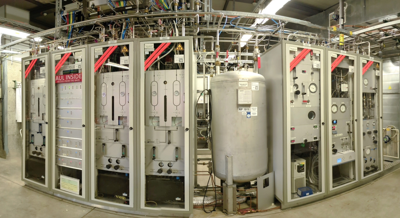
Nowadays, the new objective is to extend the use of gas recirculation plants to small and medium size experiments as well as to laboratory application. Indeed, a considerable contribution to GHG emissions is due to setups used for detector upgrade projects, R&D activities, detector production tests and longevity studies. Furthermore, in some European institutes the purchase of GHG is already subject to strict rules and in some cases, it is difficult to get enough gas for testing purpose. A recirculation system will allow to testing detectors in laboratories. To minimize such emissions, a compact and flexible recirculating gas system was developed (2). The small recirculating system was conceived as a single euro-rack containing the essential gas systems modules such as humidifier, pump, distribution, gas analysis, purifier, and control PLC. The system was designed to operate several detectors with volumes up to several tens of litres. Figure 1 shows the front and rearview of a small recirculation unit. Several of these recirculation systems have been built in the last years and are used for RPC, CSC, GEM detectors in laboratory set-ups, test-beam set-ups and at the CERN Gamma Irradiation Facility (GIF++).
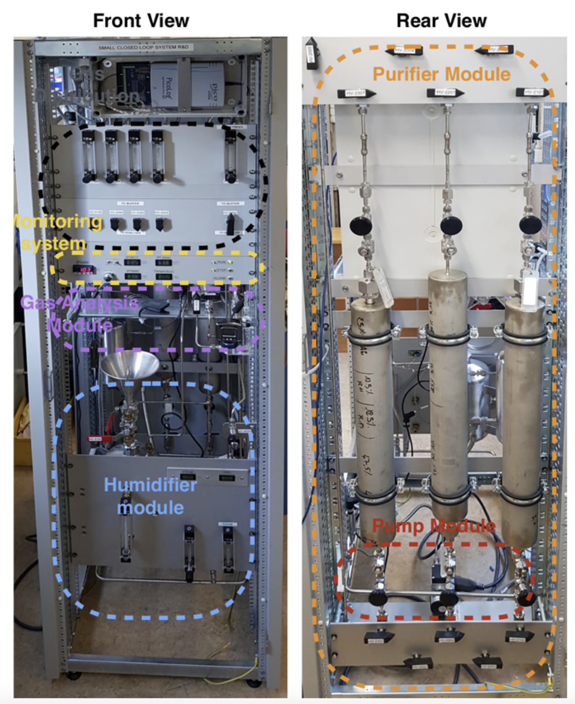
Figure 1 Front and rear view of the small gas mixture recirculation unit.
Together with the development and commissioning of a small recirculating system, an even smaller and simpler recirculating unit was designed with the goal of having a portable recirculation system for few detectors as simple and economically suitable for small institutions such as schools, universities, and CERN laboratories (3). The system (Figure 2 is an example) should also be kept as simple as possible, and the operation should require the least amount of manual intervention.
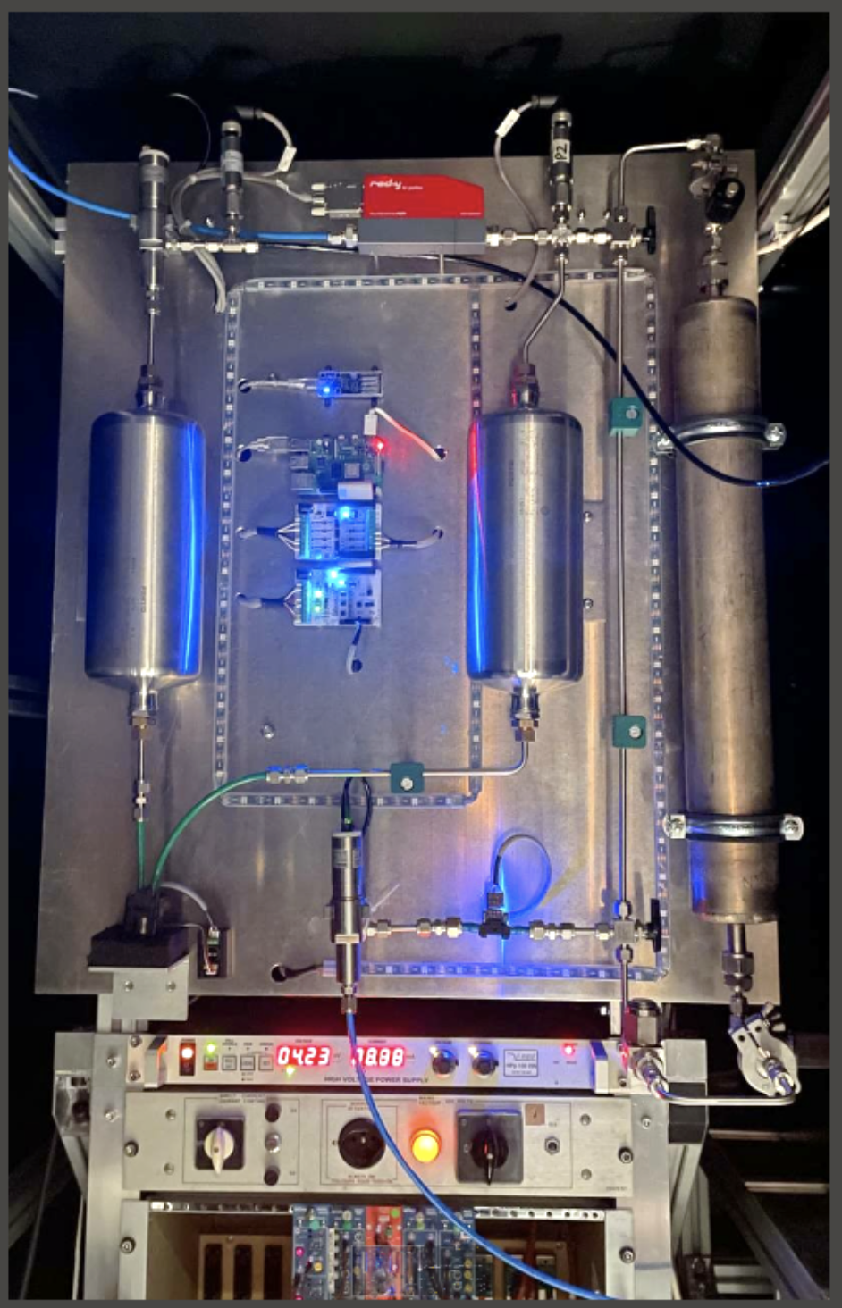
Figure 2: An example of a portable recirculation system explored for certain applications.
In some cases, depending on the material used during construction, particle detectors can be gas tight but at the same time permeable to impurities that cannot be filtered by gas purification modules such as N2, or, for example, the detector may need a higher fresh gas injection following results of long-term validation tests. In these circumstances, the gas recirculation rate is limited by the need to avoid an excessive accumulation of impurities in the gas stream. The mixture can be collected from the exhaust of the gas recirculation plant and sent to a dedicated gas recuperation plant able to extract a specific mixture component.
Gas recuperation plants allow to reduce the usage of fresh gas injected into gas recirculation plants and therefore to further reduce the GHG emissions. However, they introduce a second level of complexity in addition to the gas recirculation plants. Moreover, given the specificities of the gas mixture used by particle detector systems no industrial apparatus currently exists to address our needs. Dedicated R&D studies are required for the design of a recuperation plant and similarly for the definition and tuning of the gas mixture monitoring tools.
The separation of fluorinated gases is carried out mainly through membranes, absorbers, or distillation. For example, the first CF4 recuperation plant was installed at CMS in 2012, and it now has a recuperation efficiency of about 70%. CF4 is separated from a CF4/Argon/CO2 mixture in three stages: first, a membrane, then absorption of CO2 on molecular sieve 4 Å and finally with pressure swing absorption cycles on molecular sieve 13X. During 2023, more than 250 m3 of recuperated CF4 were used compared to 110 m3 of fresh CF4.
New recuperation plants were recently developed for CF4 at LHCb-RICH2 and R134a for RPC detector systems (used at ALICE, ATLAS and CMS).
The R134a recuperation plant is extracting R134a greenhouse gas from the RPC standard mixture (i.e. R134a/iC4H10/SF6). The first version of this plant is installed at CMS (Figure 3). During the commissioning period from July to November 2023, it allowed to recuperate and reuse about 1 ton of R134a. For the case of the RPC standard mixture, the gas separation process is complicated by the fact that R134a and iC4H10 form an azeotrope, i.e. a mixture that cannot be separated by simple distillation. To overcome this complication, firstly the azeotrope, i.e. the R134a and iC4H10 mixture, is totally liquefied, and it is sent to a warm buffer volume kept at a few degrees Celsius above 0 ◦C where the R134a separation from iC4H10 occurs. The R134a recuperation efficiency is about 80%, allowing an important reduction of both emissions and operational costs. A further upgrade with the addition of an additional stage for the recuperation of SF6 is also under study.
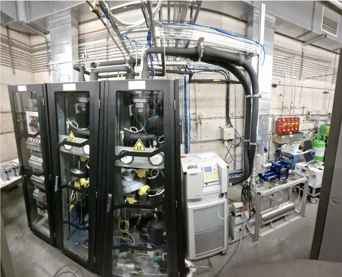
Figure 3: R134a recuperation system installed at CMS.
A new recuperation plant is under construction for the C4F10 used by the LHCb-RICH1 detector. It will replace the existing one that dates back to the times of the DELPHI experiment at LEP. The new plant will give significant improvements both on the recuperation efficiency and in the quality of the recuperated gas.
Of course, the most effective and final solution would be the replacement of currently used greenhouse gases with new eco-friendly alternatives. It is an important step for the long-term operation of gaseous detectors for existing and future experiments. An intense R&D activity is already ongoing for many years in the detector community for finding environmentally friendly replacements of R134a, SF6, CF4 and C4F10. However, finding a suitable replacement for the current detectors at the LHC experiments is particularly challenging because most of the infrastructure (i.e. high voltage systems, cables, front-end electronics) as well as the detectors themselves cannot be easily replaced and therefore cannot be adapted to cope with the different characteristics of the new eco-friendly gases. In addition, the new eco-friendly replacements have been developed following requirements from the refrigerants and obviously not for particle detectors.
For the case of the RPC detectors (using R134a, SF6) encouraging results for a possible mitigation and also a transition period, have been obtained with the addition of up to 30-40% of CO2 to the standard gas mixture (6). The detector performance is comparable with the ones obtained with the standard gas mixture, indicating a possible midterm solution for reducing the GHG emissions. This mixture is nowadays used by the ATLAS-RPC detector system.
References:
- https://indico.cern.ch/event/1386095/ CERN EP-DT seminar “Recuperation systems for fluorinated gas at the CERN LHC Experiments”
- https://doi.org/10.1088/1748-0221/12/10/T10002 “A portable gas recirculation unit"
- https://doi.org/10.1016/j.nima.2023.168095 "Gas recirculation systems for RPC detectors: From LHC experiments to laboratory set-ups”.
- https://doi.org/10.1016/j.nima.2023.168088, “Performance studies of RPC detectors operated with C2H2F4 and CO2 gas mixtures”.