![]()
The new ALICE Fast Interaction Trigger
To reach Run 3 physics goals, ALICE (A Large Ion Collider Experiment) [1] must collect all minimum-bias data for an interaction rate (i.e., number of collisions each second) of 50 kHz for Pb–Pb and up to 1 MHz for pp collisions. This is two orders of magnitude greater than the Run 2 data rate. Therefore, all ALICE sub-detectors and systems, especially the readout, have been upgraded to meet this challenge. While many upgraded ALICE detectors operate in a continuous readout mode (ITS, MFT, ZDC, TOF, MCH, MID, TPC), some (TRD, CPV, HMPID, EMCAL, DCAL, PHOS) require a fast trigger. This is the primary role of the Fast Interaction Trigger (FIT) [2], one of three new detectors [3] added to ALICE during the second long shutdown of the LHC. In addition to triggering, FIT will also monitor luminosity, provide a start for Time-Of-Flight particle identification, reconstruct forward particle multiplicity, centrality, reaction plane, and provide important data for diffractive physics measurements.
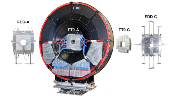
Figure 1. Photos of the FIT detectors, located at 17 (FFD-A), 3.2 (FT0-A and FV0), -0.8 (FT0-C), and -19.5 meters (FDD-C) from the Interaction Point. Credits: Wladyslaw H. Trzaska
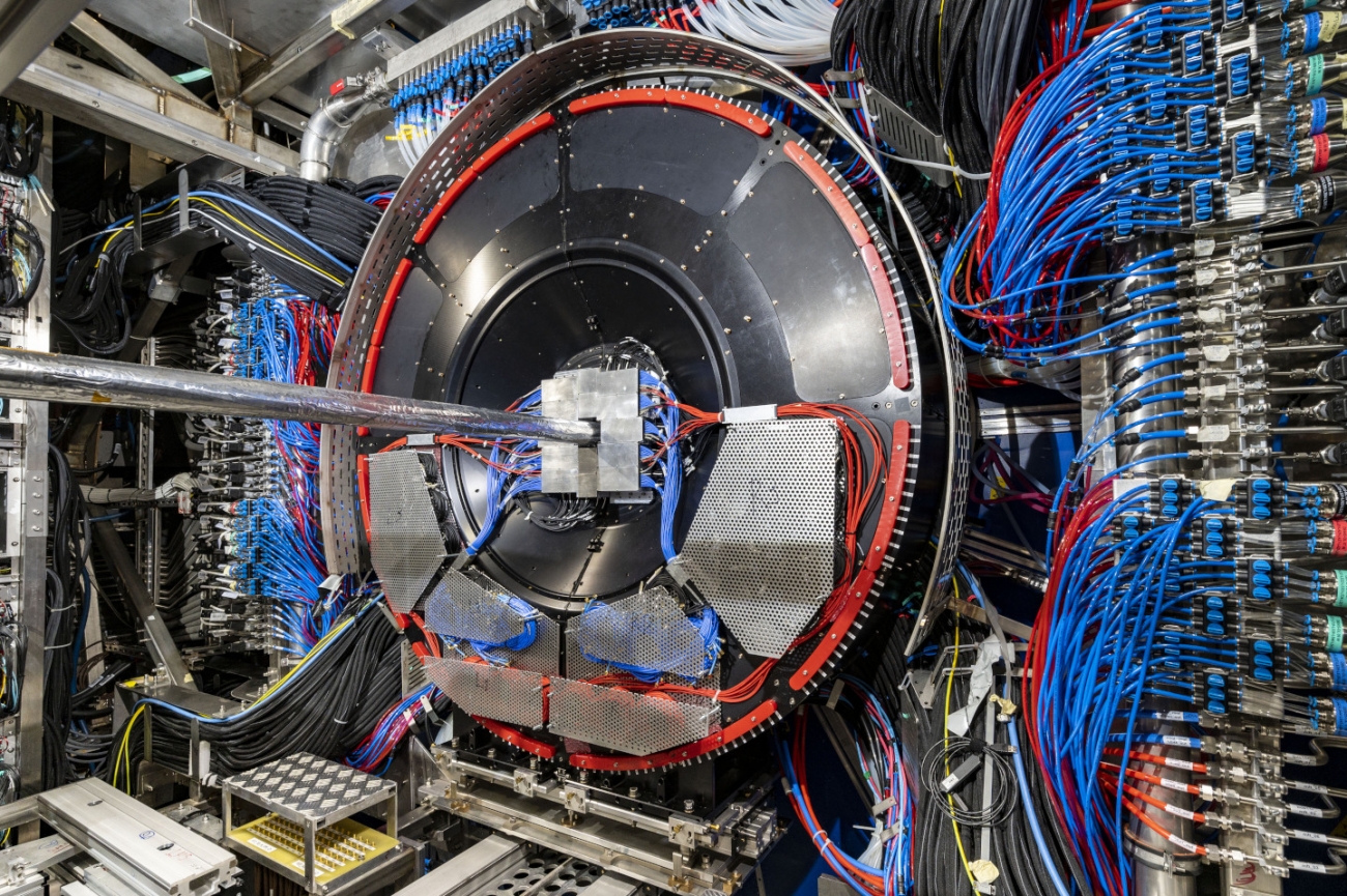
FIT consists of three detector systems arranged into five groups surrounding the beam pipe at four different locations on both sides of the Interaction Point (IP). FT0 is the fastest of the trio. It has a modular design. Each module consists of four quartz Cherenkov radiators attached to a modified Planacon MCP-PMT [4] operating as four independent photosensors.
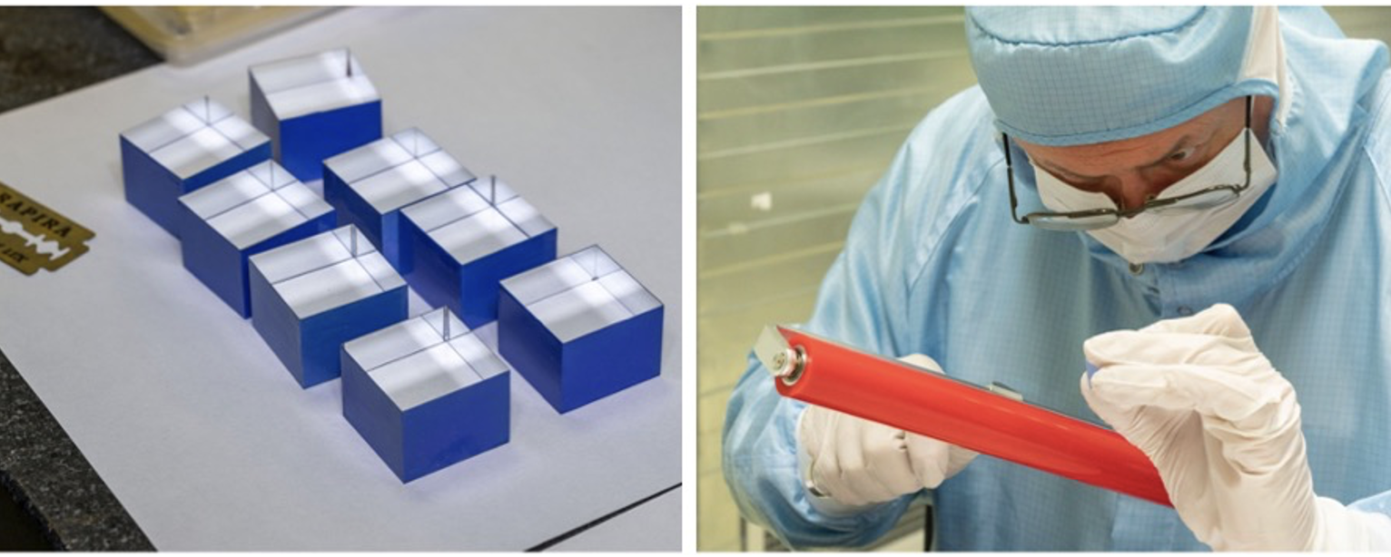
Figure 2. Preparation and inspection of FT0 quartz Cherenkov radiators. Credits: Wladyslaw H. Trzaska
FT0 generates minimum-bias triggers and measures luminosity. The generation of the FIT trigger is fully digital. Here, the challenge was to reduce the total latency of the trigger to below 425 ns. Half of that delay comes from the connecting cables, so the trigger hardware and firmware must complete signal digitisation and evaluation in just over 200 ns [5].
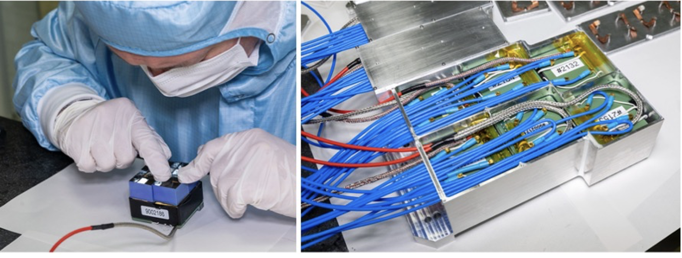
Figure 3. Assembly of FT0 modules in a cleanroom at CERN. Credits: Wladyslaw H. Trzaska
To verify the IP location, the online time resolution of FT0 must be better than 50 ps. For high-multiplicity events, the offline RMS resolution will be 15 ps. The amplitude generated by a minimum ionising particle (MIP) in FT0 modules is 7.5 mV. This exceptionally low amplification was chosen to ensure linearity over the required dynamic range and to guarantee sensor operation throughout ALICE lifetime. Consequently, there is a 3 mV threshold on the input of the FIT electronics.
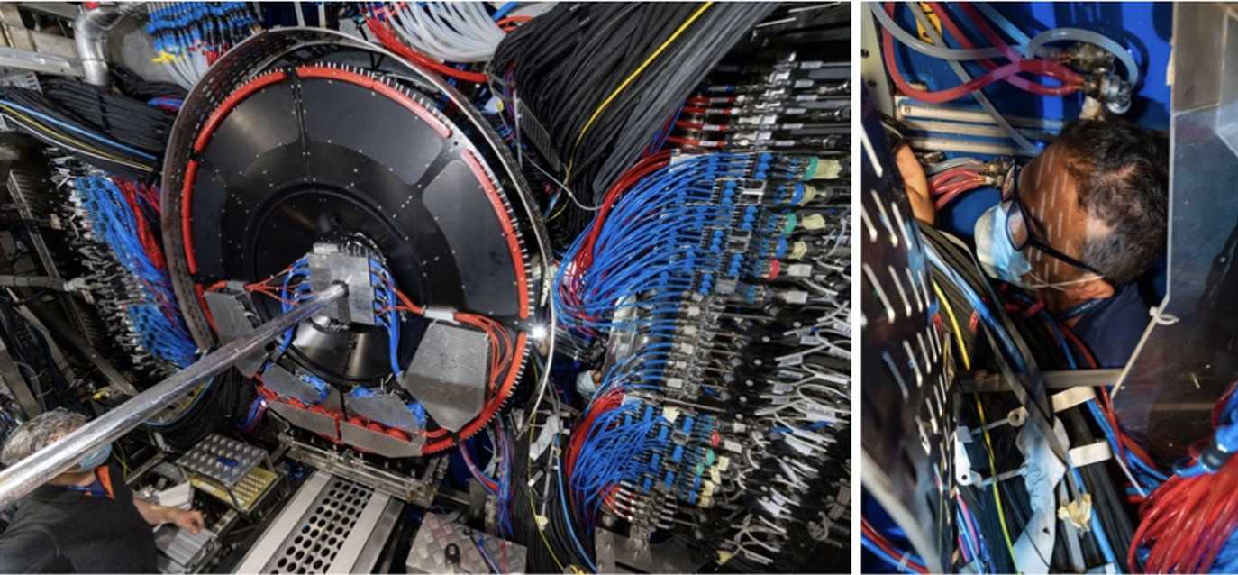
Figure 4. FIT-A (FV0 and FT0-A) approaching the final position under a watchful eye of a member of the ALICE technical team, holding a flashlight in his hand. Credits: Wladyslaw H. Trzaska
High cost is the main drawback of the MCP-based technology. Therefore, FV0, the largest FIT detector, is a segmented scintillator disk. FV0’s large acceptance is needed for multiplicity, centrality, and event plane determination. These parameters are essential for the characterisation of heavy-ion collisions – the primary focus of ALICE physics. Because of the significant size and many nucleons involved, there are vast differences between central, semi-central, and peripheral collisions.
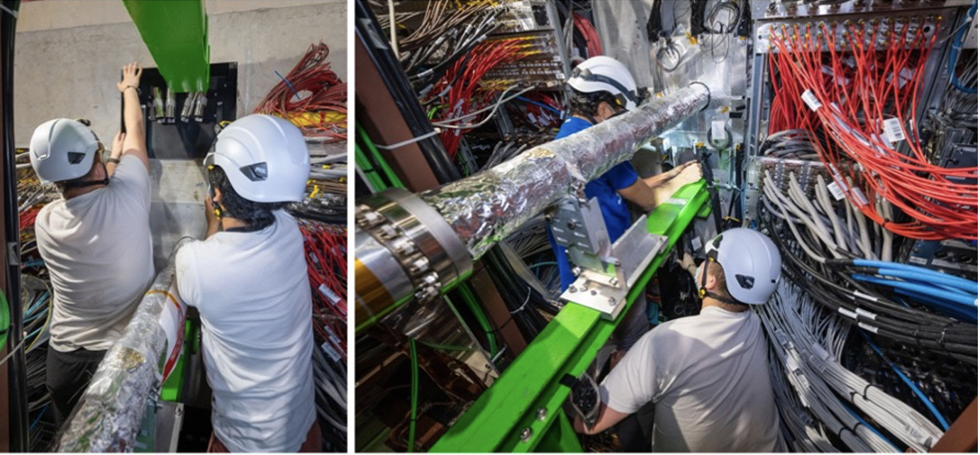
Figure 5. Installation of FDD-A. A denotes the position on the ATLAS side of the IP. Credits: Wladyslaw H. Trzaska
The third detector, the Forward Diffractive Detector (FDD) [6], is placed far from the IP and measures particles at high pseudorapidity, aiding in background monitoring and diffractive physics. Diffractive and photon-induced processes are characterised by the presence of rapidity-gaps, regions in pseudorapidity where no particles are produced. These types of collisions are interesting because they offer alternative windows to the fundamental properties of QED and QCD. For example, the diffractive photoproduction of vector mesons is a clean tool to search for saturation and shadowing effects. They are the subject of many recent measurements and predictions. The FIT detectors, with their broad pseudorapidity coverage and low signal threshold, are ideally suited to efficiently tag the presence of gaps in particle production.
Design and construction challenges
The need for a fast interaction trigger was clear from the beginning of the upgrade project. Nevertheless, the actual design could start only when the final ALICE requirements and space constraints became known. FIT evolved from four ALICE detectors used in Run 2: T0, V0, FMD [7] and AD. The old detectors had sensors in eleven points along the beampipe. The FIT upgrade could use only four places and yet maintain the same functionality.
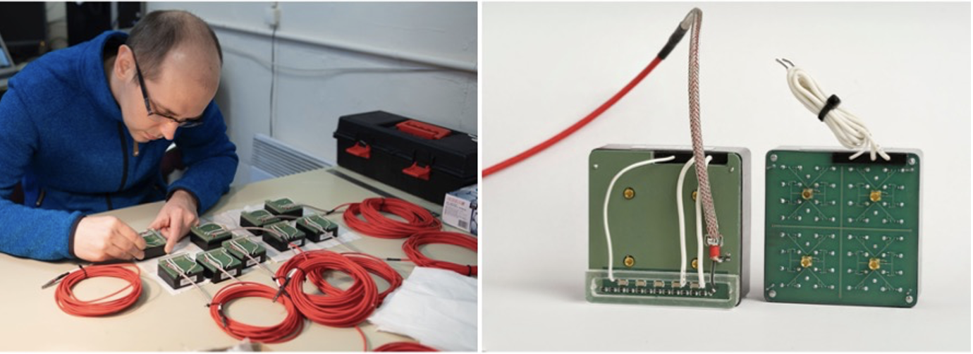
Figure 6. The final assembly of the MCP-PMT modules. FT0 uses photosensors with a modified backplane. Credits: Wladyslaw H. Trzaska
Because of the very congested central area, the FT0 detector had to opt for MCP-based sensors. It was a bold move as this technology was still not tested on a larger scale, and the available products had serious crosstalk problems. However, in close collaboration with the producer, we were able to solve them by redesigning the backplane of the sensor according to the FIT specifications.
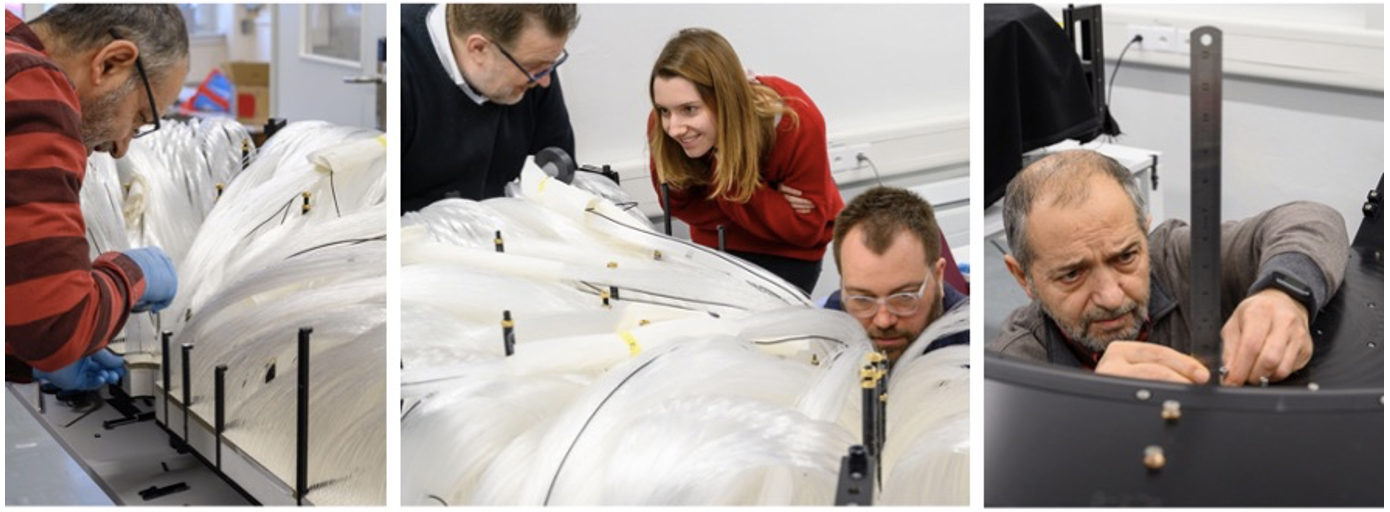
Figure 7. FV0 uses a novel light collection system resembling a well-combed angel’s hair. Credits: Wladyslaw H. Trzaska
Reduction to 25 ns of the bunch crossing time for ALICE required significant improvements in FIT scintillator detectors. The mid-sized FDD solved that problem by using the fastest available wavelength shifters. At the same time, FV0 – the largest FIT component – pioneered a novel light collection system [8], guaranteeing excellent uniformity and time resolution of the order of 100 ps.
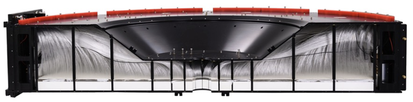
Figure 8. Photograph of an FV0 half with the side covers removed. Credits: Wladyslaw H. Trzaska
The size of the FV0 posed a mechanical challenge as well. The design of a thin, lightweight shell to contain a 300 kg detector was non-trivial and required the manufacturing capability of an aerospace company. The outcome is stunning; FV0 is perhaps the most beautiful of all ALICE detectors with its elegant slim shape and the black-anodised aluminium surface.
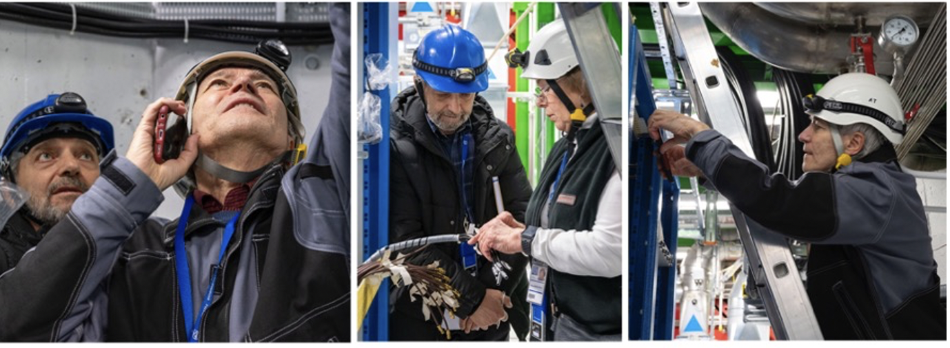
Figure 9. Installation of FIT cables and patch panels in the racks. Credits: Wladyslaw H. Trzaska
A large underground LHC hall, tightly filled with experimental equipment, pumps and cooling devices, is a noisy environment, both acoustically and electromagnetically. Therefore, special care must be taken to transmit FIT signals over tens of meters while maintaining the low 3 mV threshold. Our solution is the use of doubly shielded, thick cables. The significant magnetic fringe field at the location of FIT electronic racks forced us to add shielding and equip the crates with custom-made field sensors. To monitor the performance and look for signs of ageing, all the FIT detectors use Laser Calibration Systems. However, optical fibres are also prone to radiation damage. To counter that, all fibres in the vicinity of the beam pipe are radiation hard.
Installation and commissioning
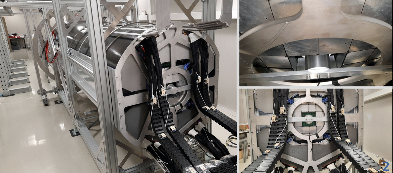
Figure 10. The mock-up of the ALICE inner barrel with the actual detectors during the insertion drill. The square-shaped FT0-C modules surround the dummy beampipe. Credits: Maciej Slupecki
FT0-C, where C denotes position on the CMS side of the IP, was the first FIT array installed. At that time, FT0-C was already fully integrated with MFT. The insertion, combined with the mounting of the ITS, was the most challenging operation during the upgrade of the ALICE setup. This required meticulous rehearsals involving all the tools and procedures using a life-size purpose-built mock-up. In addition, the actual insertion was done with the fragile beryllium beampipe already baked and under vacuum with access to the small inner opening of the TPC only from one side, adding to the complexity of this operation.
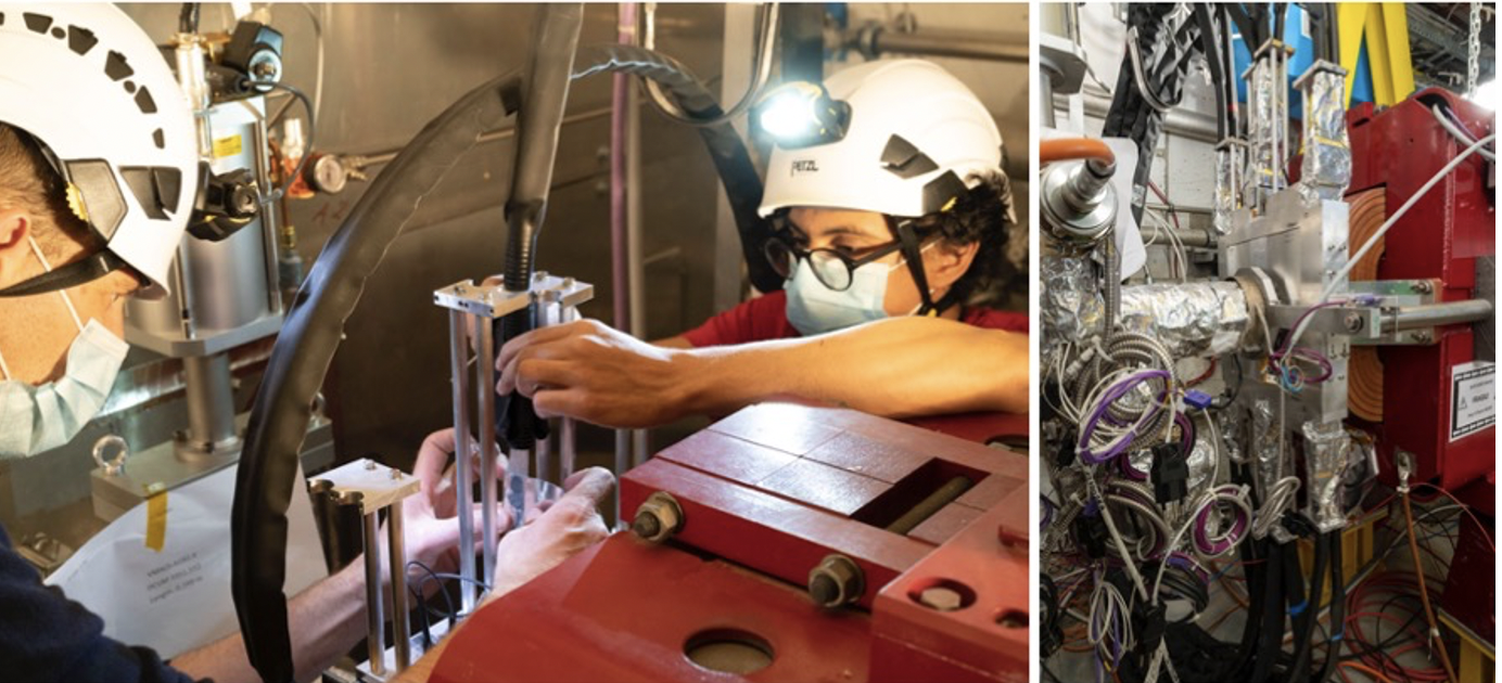
Figure 11. Installation of FDD-C in the LHC tunnel, right next to the ALICE cavern. Credits: Wladyslaw H. Trzaska
The FDD-C array installed next is in the LHC tunnel, just outside the ALICE cavern. There was a small time window for this operation. As there is no open passage between the cavern and the tunnel, the installation team had to be on both sides simultaneously. In comparison, the placement of FDD-A was relatively straightforward.]
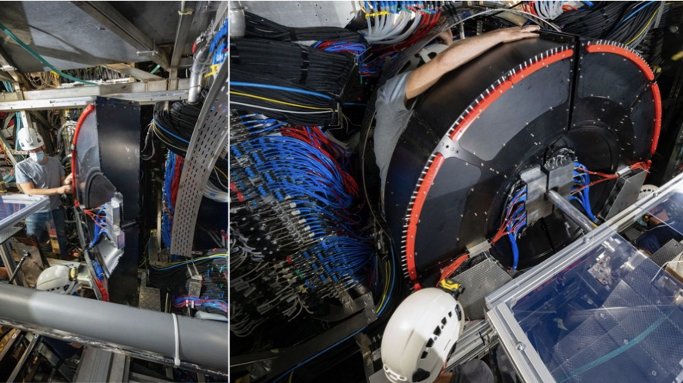
Figure 12. Insertion of FIT-A required acrobatic skills from the technical support team. Credits: Wladyslaw H. Trzaska
Still, the most demanding for our team was installing FIT-A, the largest element of FIT consisting of FV0 and the FT0-A array. The procedure started with the transport of the pre-commissioned halves from the surface laboratory to Point 2. It was done in the early hours of the morning with a slow-moving truck. A 5-ton iron slab was placed under the detector boxes to guarantee a smooth ride. The convoy proceeded with a top speed of 15 km/h.
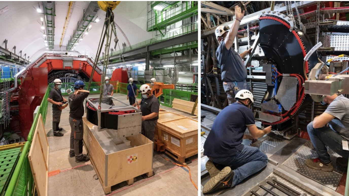
Figure 13. Unpacking of FIT-A and lowering it to the ALICE miniframe. Credits: Wladyslaw H. Trzaska
Once at Point 2, all sensors were retested. There was no damage during the transportation. The detector was packed again and lowered to the ALICE cavern. After attaching the lifting jigs, FIT-A was moved to the miniframe and fixed to the insertion rails.
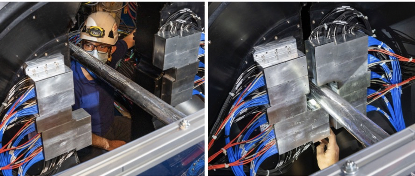
Figure 14. The FIT-A halves are closing in around the exposed ALICE beampipe. Credits: Wladyslaw H. Trzaska
It took nearly 12 hours to place FIT-A into the final position. At first, the progress was fast. The closer we got to the unprotected and very fragile beampipe, the slower was the pace. In this highly cramped area, we had to rely on the ALICE technical crew's watchful eyes, experience, and dedication to accomplish the task. Following the installation, all channels were checked, and the commissioning started. Having been installed as the last of the new detectors, FIT, a luminometer and trigger detector, must be the first to be turned on for the LHC beams.
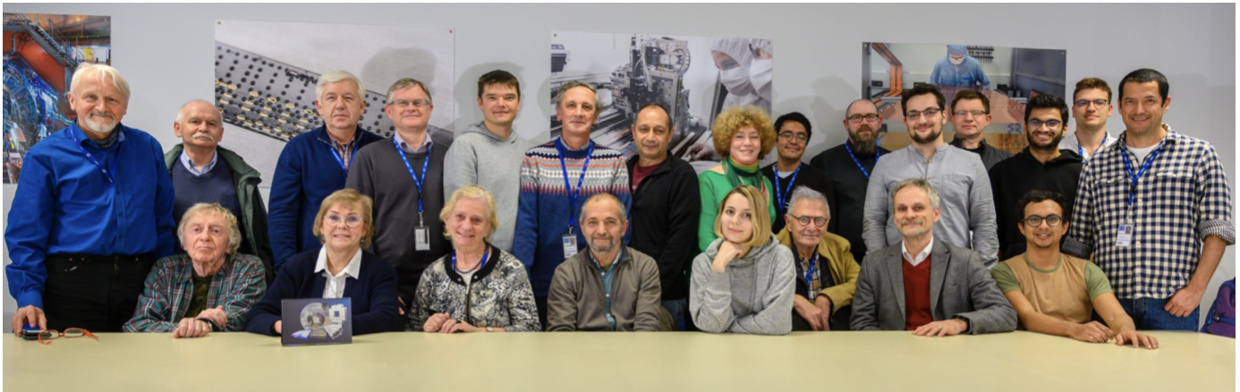
Figure 15. FIT Collaboration meeting at CERN in November 2019. Credits: Wladyslaw H. Trzaska
FIT Collaboration consists of sixty-four scientists representing 17 institutions from Austria, Czech Republic, Denmark, Finland, Mexico, Poland, Russia, and the United States. FIT is expected to serve ALICE till the end of Run 4.
References:
- The ALICE Collaboration, The ALICE experiment at the CERN LHC, 2008 JINST 3 S08002, https://doi.org/10.1088/1748-0221/3/08/S08002
- M. Slupecki for the ALICE Collaboration, Status of the Fast Interaction Trigger for ALICE Upgrade, PoS(ICHEP2020)779, https://pos.sissa.it/390/779/pdf
- W.H. Trzaska on behalf of the ALICE Collaboration, New ALICE detectors for Run 3 and 4 at the CERN LHC, NIM A 958(2020)162116, https://doi.org/10.1016/j.nima.2019.04.070
- Yu.A. Melikyan, et al., Performance of Planacon MCP-PMT photosensors under extreme working conditions, NIM A 952(2020)161689 https://doi.org/10.1016/j.nima.2018.12.004
- D. Finogeev et al., Readout system of the ALICE Fast Interaction Trigger, JINST, 15 (9), C09005 https://doi.org/10.1088/1748-0221/15/09/C09005
- S. Rojas-Torres for the ALICE Collaboration, The Forward Diffractive Detector for ALICE, PoS(LHCP2020)221 https://pos.sissa.it/382/221/pdf
- CERN-LHCC-2004-025 ALICE-TDR-011, 10 September 2004 https://cds.cern.ch/record/781854/files/lhcc-2004-025.pdf
- V. Grabski, New fibre read-out design for the large area scintillator detectors: providing good amplitude and time resolutions, https://arxiv.org/abs/1909.01184v1