![]()
ALICE trigger system: Present and Future
The purpose of any trigger system is to select an event sample strongly enriched in physics processes of interest, while rejecting those not of interest, and to do so in such a way as to make efficient use of the available detectors.
The prime objective of the ALICE experiment is a comprehensive study of ultrarelativistic heavy ion interactions at LHC energies. The strong-interaction cross-section for such interactions is very large (σ = 8 barns), but, compared with what is achieved in pp collisions, the maximum luminosities available in ion-ion collisions are modest; to date, the maximum luminosity attained in Pb Pb interactions is 1027 cm-2 s-1, compared with 1034 cm-2 s-1 at the ATLAS and CMS intersection regions in pp interactions. The physics aims of the ALICE experiment are markedly different from those of the other experiments at the CERN LHC, leading to a different approach to triggering. In addition, heavy ion interactions are characterised by very high event multiplicities. The number of charged particles produced per unit of rapidity at mid-rapidity in central collisions can reach 2000 at √s =5.02 TeV, indicating that the total multiplicity would run to many thousands of charged particles. Measuring particle momenta and providing charged particle identification in such a high density environment is very challenging, and governs the choice of detector technologies in the experiment.
The physics signatures of interest in heavy ion collisions are either very general or very difficult to extract from background. Bulk features can be measured from essentially all events and therefore may be addressed by a Minimum Bias trigger, while other features, such as charm or beauty decays, are extremely difficult to extract at trigger level owing to the high levels of background.
Runs 1 and 2
Trigger decisions are made to meet several possible latencies in ALICE [1}. The situation for Runs 1 and 2 is shown in Table 1.
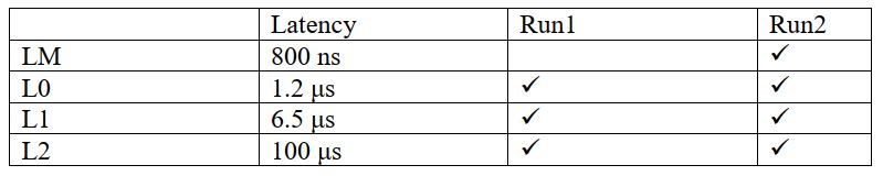
Table 1. Latencies for each trigger level in the ALICE trigger system, as used in Runs 1 and 2.
The LM level, introduced in Run 2, has the purpose of providing a rough minimum bias-like trigger to be used to activate (“wake-up”) the TRD electronics, which are kept switched off when not required in order to reduce heat dissipation. The “main” part of the trigger starts with L0, available since Run 1, for which most of the trigger inputs are timed.
Trigger inputs can be accepted at each of these three latencies, to a maximum of 24 (LM/L0), 20 (L1) and 6 (L2). The allowed trigger conditions are a programmable combination of ANDs of different trigger inputs, with other trigger operations (e.g. OR, negation) only possible for a subset of the inputs. The ALICE trigger takes into account the fact that some detectors read out much more quickly than others by introducing the concept of a trigger cluster. A trigger cluster is a group of detectors that read out together. The detectors in the forward muon spectrometer have well-matched readout characteristics and can read out much more quickly than the slowest of the central detectors. For this reason, an efficient way to manage readout is to allow the forward muon detectors to read out both separately, in a “muon cluster”, and in association with the central detectors, resulting in larger integrated luminosities for the forward muon cluster. The decision as to which cluster is to read out (whole detector or forward muon cluster) is taken dynamically, on an event-by-event basis, depending on availability of detectors. Other uses of the separate cluster concept include separating a single detector into a cluster of its own for debugging purposes.
ALICE detectors are for the most part not pipelined, reflecting the lower interaction rates at the ALICE intersection region. This implies that detectors ned to employ a BUSY mechanism to protect themselves from spurious signals during readout operations. Each detector sends a maximum of two BUSY signals to the CTP (to allow for detectors with separate electronics on each side of the interaction region).
These requirements determine the characteristics of the Run1/Run 2 trigger system. The Central Trigger Processor (CTP) consists of six different board types, all implemented in 6U VME, housed in a VME crate with a custom J2 backplane for transmission of trigger signals from one board to another. A seventh board type, the Local Trigger Unit (LTU), serves as the interface between the CTP and the detectors, collecting BUSY signals from the detectors and distributing trigger signals to them. There is one LTU per detector.
The architecture of each board type is similar. The LTU, which was produced first, is at once the prototype and the most complicated board, because it also allows an emulation of the whole trigger system, generating complete trigger sequences suitable for exercising detector readout when in standalone mode, decoupled from the CTP. The board has two Field Programmable Gate Arrays (FPGAs). An Altera EPM3512, visible at the top right of the board (see fig. 1) controls the VME traffic on the J1 backplane, carrying VME commands from the VME processor for the crate to the board, including those needed to configure the firmware for the other FPGA. This is an Altera Cyclone EP1C20, and it executes the trigger logic on the board. It is situated in the centre of the board. Underneath it is a large flash memory chip where the current firmware is stored; its contents can be updated through VME. The FPGA loads this firmware at power-up. A small collection of chips at the bottom right of the board run Philips Inter Integrated Circuit (I2C) protocol to allow monitoring of voltages and temperatures on the board. These features are present on all the boards, with varying arrangements of ancillary electronics to fulfil the specific functions of each board.
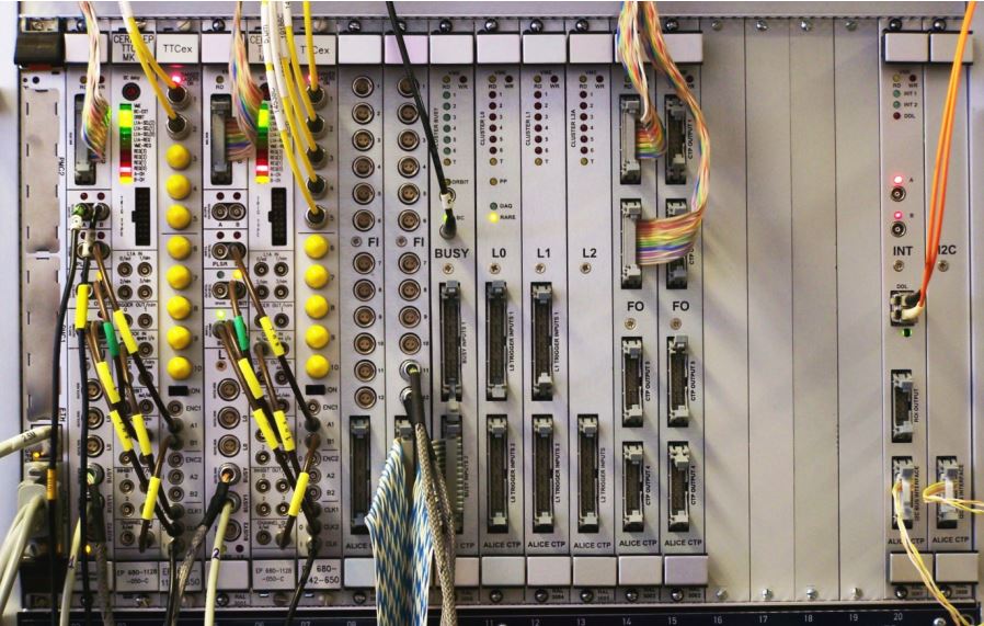
Figure 1. CTP layout for Run 1. The CTP uses six boards. Trigger inputs are sent on LVDS cables to the Fan-In boards (FI) and from there to the trigger level boards on flat cables. BUSY signals are collected and processed on the BUSY board. The L0 board is the starting point for trigger generation. The L1 and L2 boards add further trigger conditions to the trigger analysis that has been initiated. The decisions are fanned out to the detectors from the connectors on the Fan-Out boards (FO). The INT board provides trigger data for the event for trigger performance monitoring.
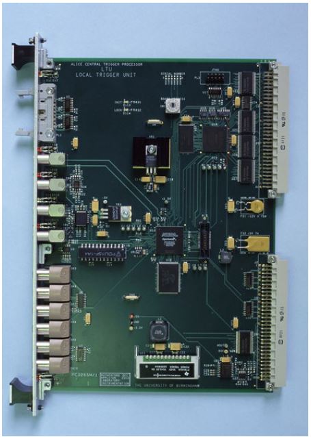
Figure 2. The Local Trigger Unit. The two FPGAs are visible at the top right and at the centre of the board. The Cyclone FPGA has a flash memory directly below it. The board is described in more detail in the text.
The trigger proved very reliable during Runs 1 and 2. Figure 2 shows the cumulative yields for different types of trigger in Run 1. The bulk of the data taken were minimum bias, and in addition triggers were taken using the forward dimuon spectrometer (“dimuon”), using the electromagnetic calorimeter to flag jets (“EMCAL jet”) and using the Transition Radiation Detector (TRD) to flag electrons with pT > 1 GeV/c.
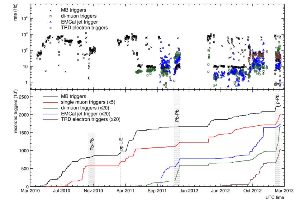
Figure 3. Trigger performance in Run 1. The integrated rates for several different trigger types are shown as a function of time. [2]
Prospects for RUN 3
In Run 3, the ALICE strategy is to focus on rare probes accessible using the ALICE strengths in particle identification and momentum reach down to very low pT [3]. These include production of heavy quark states, heavy quarkonia, thermal photons and dileptons, the interaction of jets with the medium, and the production of exotic nuclei. Such a physics strategy does not lend itself very well to conventional trigger algorithms, as there are no trigger selections that can lead to major enrichments of the heavy flavour content of the selected sample. Enrichment can only be achieved through a full reconstruction of the decay, keeping those events which show candidates passing a series of already specialised selections.
A few years ago, such a procedure would have been considered completely unworkable, but rapid improvements in computer performance, coupled with dramatic decreases in cost per processor unit, mean that today it is possible to assemble an array of processors (“high level trigger”) of sufficient size to have an aggregate throughput that keeps up with the data rate. In ALICE, this also means increasing the interaction rate from ~8 kHz for PbPb collisions in Runs 1 and 2 to ~50 kHz in Run 3.
Many (but not all) of the ALICE detectors will have a complete overhaul of readout electronics for Run 3, moving to a system of “continuous” readout. The TPC, in particular, lends itself to this as it naturally takes some considerable time after an interaction for all the charge from the produced tracks to drift onto the anodes (about 100 μs); with an increased interaction rate, this means the events will mostly overlap. Nevertheless, a modification of the anode structure (to incorporate GEM readout) is necessary to avoid space charge buildup from the positive ions formed during gas amplification. The inner tracker and the muon chambers are also being re-equipped for continuous readout. In particular, the geometry of the inner tracker will be altered to provide layers closer to the interaction point, giving improved vertex resolution. The new detector will use “Alpide” monolithic silicon pixels, but will not have trigger functionality.
In this environment, the task of the trigger system is in principle simplified [4]. Detectors that have not upgraded to continuous readout require a simple Minimum Bias trigger (and all detectors, whether continuous readout or not, are required to be able to operate in triggered mode). Following the latency requirements for Runs 1 and 2, trigger inputs can arrive at 850ns, 1.2 μs, and 6.5μs. However, unlike in the previous runs, each detector receives only one trigger, with a latency chosen to be suited to the detector’s readout. Detectors with continuous readout simply require a subdivision of the data stream into time intervals called heartbeats, to allow synchronization between different detectors.
A heartbeat has been chosen to coincide with one LHC orbit. The detectors are supposed to be dead time free, and therefore always capable of receiving fresh data. Nevertheless, situations can arise when detectors are unable to take data, and the detectors in this case report that the data for a given heartbeat are not satisfactory. These messages are collected into a heartbeat map, which summarizes the status of the detector (or, more specifically, those parts of it running continuous readout) for a given heartbeat. The assembly of heartbeat maps is a slower operation than the determination of the busy status of detectors; it can take several hundred microseconds to compete the whole ensemble of heartbeat statuses from all the participating detectors. Once the heartbeat map is available, the data from a given detector in that heartbeat is either kept or discarded according to programmable actions defined for different heartbeat map conditions.
Advances in FPGA technology between the time when the Run 1 and Run 3 hardware were designed have meant that the whole trigger logic can now be handled by a single FPGA, in this case a Xilinx Kintex Ultrascale (XCKU040FFVA1156) . This obviates the need for a special backplane, as all the logic is performed on one board, with a major improvement in flexibility, but makes the management of inputs to the board more challenging. The board occupies four 6U VME slots in order to allow all the connections to be made. The board is shown in fig. 4. Despite the simpler approach to the new detectors, the requirements that (i) some detectors should continue to receive triggers for each event as before and (ii) that all detectors, including those earmarked for continuous readout, should also be capable of conventional triggered operation, makes the board considerably more sophisticated than its predecessors. The partial replacement of the RD-12 TTC by the more powerful TTC-PON also makes the system more complicated, and more powerful.
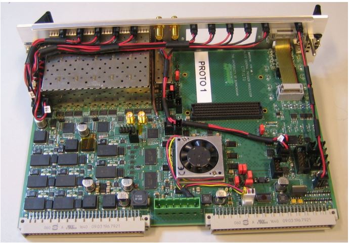
Figure 4. Level 3 trigger board, top view. The Xilinx Kintex Ultrascale FPGA is visible (with fan) near the middle of the board.
Summary
The ALICE trigger system has served the experiment well in Runs 1 and 2, allowing a number of features designed to optimize the use of the detectors, such as dynamic partitioning and the use of “detector clusters”. In run 3 the trigger system will have a major upgrade to prepare for continuous readout, whilst retaining backward compatibility as not every detector will upgrade.
References
- K. Aamodt et al, The ALICE experiment at the CERN LHC, JINST 3 (2008) S08002
- B. Abelev et al. Performance of the ALICE Experiment at the CERN LHC, Int. J. Mod. Phys. A29 (2014) 1430044
- B. Abelev et al. ALICE Upgrade Letter of Intent, CERN-LHCC-2012-012
- B. Abelev et al., Upgrade of the Readout and Trigger System, CERN-LHCC-2013-019