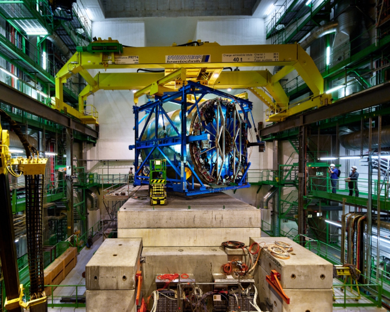
The upgraded ALICE TPC

The ALICE time projection chamber (TPC) is a big, gas-filled cylinder (with a hole in the centre to accommodate the silicon tracker), where the charge produced by ionising radiation is projected onto detectors arranged in the two endplates. Therefore, it is a true 3-dimensional tracking device which also, by recording many signals along the trajectory of each particle, is able to identify them. The detectors on the endplates used to be multi-wire proportional chambers, 72 in total, which have now been replaced by GEM-based detectors. The new devices, together with new readout electronics that feature a continuous readout mode, will allow to record all tracks produced at collision rates of 50 kHz in the LHC Pb-Pb system. The load on the chambers under these conditions is expected to be as high as 10 nA/cm2, and GEM detectors are able to cope with this. But will these devices perform as nicely as their predecessors?
Fig 1. Schematic view of the ALICE TPC upgraded with GEMs.
In order to get a positive answer to this question, several years of intensive R&D were necessary, since the large number of positive ions produced at the detectors would lead to excessive track distortions. This issue, combined with the necessity of keeping excellent dE/dx resolution for particle identification, and the imperative robustness against discharges, posed an exciting challenge that led to a novel configuration of GEM-based detectors, where all the requirements were finally met.
Previous implementations of GEM detectors consisted of stacks of three GEM foils with a ‘standard’ hole pitch of 140 mm, where the gain in each subsequent foil is lower than in the previous one, and finally the amplification electrons that make it through the stack are collected on an anode plane which is usually segmented into readout pads (our case) or strips. This results in a few percent of ions invading the drift volume, thus seriously distorting the drift field. In the case of this TPC, efficient ion blocking is achieved with a stack of four GEMs with two different hole pitches, 140, 280, 280, and 140 mm, and with increasing gains. Thus, most of the ions are produced deep in the stack, where a trap consisting of asymmetric transfer fields above and below the fourth GEM prevents them from escaping into the drift volume. Yet, a moderate gain is applied on the first two foils in order to preserve the primary electron statistics for good dE/dx resolution. This configuration of a GEM stack turns out to be robust against discharges under a Ne-CO2-N2 gas mixture, thanks to the splitting of the gains across four GEMs instead of three.
‘GEMs are great, but you can’t power them’, said, long time ago, a colleague from our field. Let’s put this statement into context: most GEM detectors are operated with a single high voltage (HV) power supply connected to a resistor chain to supply the decreasing voltages to the GEM stack. This concept allows for a safe operation of the detector, since in case of a discharge, the voltage through the whole chain would decrease synchronously, and no voltage increase happens across any pair of electrodes. Now, this configuration has no flexibility to adjust the voltage in any individual electrode, which a large TPC requires, e.g. for fine-tuning the gain and/or the ion back flow in every stack. The use of individual power supplies for each electrode, however coupled they are, cannot prevent over-voltages in case of discharges, so this solution results, sooner or later, in the appearance of shorts across GEM foils. A real solution is provided with the use of so-called cascaded power supplies, which were developed for our quadruple stacks, in which the supply of each electrode sits on top of the previous one. This arrangement ensures safety of operation and flexibility in the choice of individual voltages.
Fig. 2. Installation of one chamber in the TPC endplate: a mounting tool is used to insert the chamber inside the field cage, rotate it and bring it back into position.
Another development for the operation of the upgraded TPC in a high luminosity environment is the development of frontend electronics with the possibility of continuously recording and shipping all signals produced in the detector. The SAMPA chip, developed for ALICE, records these signals, and digitises them at a 5 MHz sampling frequency, whereas a set of optical transmitters and receivers are used to send the data to Common Readout Unit (CRU) cards and to receive control and clock signals.
After thorough construction and testing of the new chambers and electronics around the world, LS2 was the time to proceed with the upgrade of the TPC. First, the TPC was removed from the ALICE cavern and brought, inside its blue frame, to a large clean room at the surface. For this, jacks, cranes and a huge truck were used. The chamber replacement and electronics installation took over one year. Every chamber from one side was removed using a tool that allows to manipulate them with precision, not to damage the delicate mylar strips which cover the field cage walls of the TPC. Then, the new chambers were installed in their slots, aligned, and sealed. Next, the same operation was carried out on the other side. Once the TPC was filled with gas, tests with laser, cosmic rays, and X rays were performed in sets of four chambers at a time. In July 2020, the TPC was declared ready for re-installation in the cavern.
Fig. 3. The TPC in its frame being lowered down the shaft to the ALICE cavern.
Fig. 4. The TPC being transferred from its blue frame into its position in the experiment.
The connection of all the services took most of the autumn, so that the upgraded detector can be operated and commissioned in 2021. There, for the first time, the full detector will be powered, operated, and tuned so that it can salute the first Run 3 collisions in 2022.
