![]()
The commissioning and installation of the new ALICE ITS
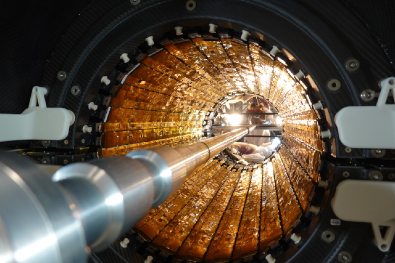
The Inner Tracking System (ITS) is the innermost detector of the ALICE central barrel. It consists of seven cylindrical layers all equipped with Monolithic Active Pixel Sensors (MAPS) named ALPIDE (ALice PIxel DEtector). The ITS allows track ing charged particles of very low transverse momentum at an interaction rate above 50kHz for lead ions increasing the data sample by a factor of 100. The upgraded ITS will reconstruct primary and secondary vertices with a 3-5 times improved impact parameter resolution compared to the old ITS. This performance is achieved thanks to the extremely low material budget of the detector layers, the high granularity allowing for excellent spatial resolution of the sensors and a closely positioned first layer at a radial distance of 22.4 mm from the interaction point. The detailed description of the new ITS has been previously reported in the EP Newsletter.
Surface commissioning
The assembly of the
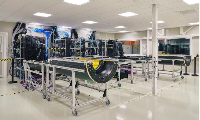
Fig 1: Overall view of the clean room in building 167. The 4 half barrels connected to the power, cooling and readout systems are visible.
The full detector assembly in half layers was completed in November 2019. Staves in layers are connected to the final version of the services, including readout units, power supply systems, Detector Control System (DCS) servers and a safety system.
The preparation and routing of cables and cooling pipes was a rather long and complex process, since everything should be optimised for fitting the space allocated in the experimental area at LHC P2. F
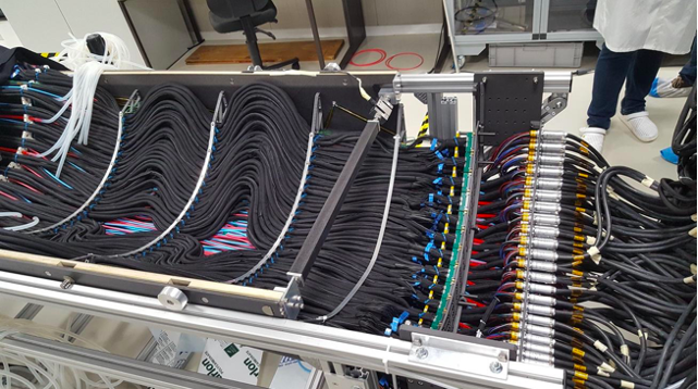
Fig 2: OB service barrel: cooling pipes, power and readout cables routing was carefully studied to fit the available space.
After the pause due to COVID-19 lockdown the preparation activities were resumed in August, starting with the verification of the functionality of the Outer Barrel Staves assembled on the layers. The ITS OB is composed of a very large number of elements (144 staves) and the layer
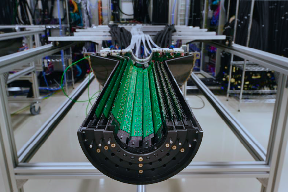
Fig 3: Front view of an IB half barrel. Cables and cooling pipes are connected on the opposite side.
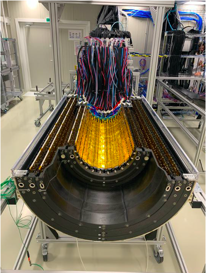
Fig 4: Top view of an OB half barrel.
Starting from August 2020 the commissioning data taking was managed by a team of experts and shifters running the detector continuously, in 24/7 shifts. Shifters were sitting in a control room adjacent to the 167 clean room, or connected remotely, when the recrudescence of the pandemics imposed travel restrictions. They were operating and monitoring the IB performance, while experts were mainly acting on the OB.
A long-term powering campaign, to spot possible infant death of staves and any service components, has been carried out and no suspicious cases have been found. This campaign required the improvement of the monitoring processes of all detector components.
All functional parameters were then optimised, starting with detailed studies to achieve the optimal configuration for power of the modules on each barrel layer. These calibration values are stored in a dedicated DataBase accessed by the DCS to configure the detector. Following the optimization of power supply, the thresholds for each sensor were characterised and tuned to calibrate the detector in view of the data taking. The characterization campaign allowed to tune the sensor thresholds to a value of 100 e− with a 2 e− precision and a chip-to-chip spread of 20 e− within an OB stave, which contains 196 sensors. An example of a Threshold map for a full OB staves, is shown in the top plot of Fig.5.
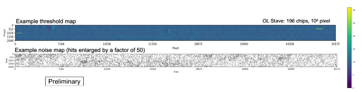
Fig 5: threshold map of a OB stave (top); noisy pixel map, with points enlarged by a factor of 50 (bottom).
Special Readout tests were performed on all the IB staves to verify the quality of the data transmission performing a measurement of the Bit Error Rate (BER). During the test, a fixed number of pixels were stimulated and the chip matrix was read out at a given rate.
After calibration both IB and OB underwent an extensive cosmic rays data taking campaign. Testing of clustering and track reconstruction algorithms started and more than 1M tracks for both IB and OB are now available for pre-alignment studies.
Cosmic rays tracks reconstructed with IB TOP half barrel are visible in FIG 6, and a real time movie showing cosmic rays hitting the same detector can be found here (link to the mp4)
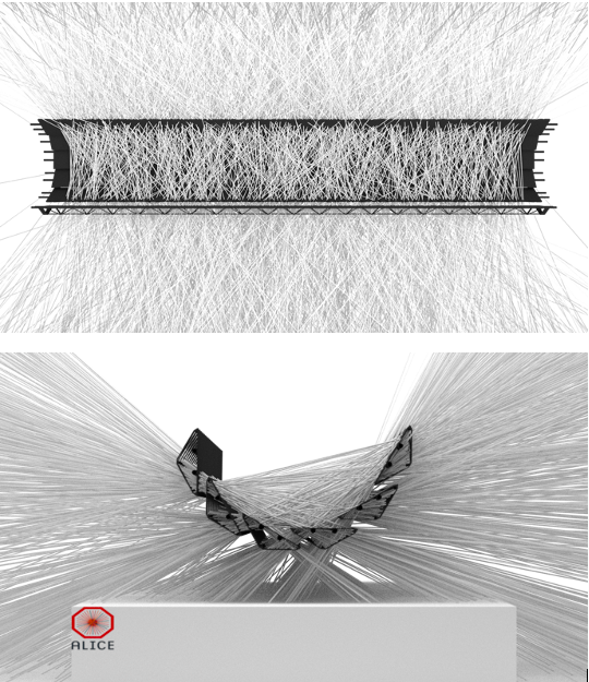
Fig 6: cosmic ray tracks reconstructed by IB TOP half barrel: top view (top); front view (bottom).
Fig 7: schematic representation of the 4 layers of OB Bottom half barrel, where the red crosses represent the clusters originating from cosmic rays hitting the detector.
Cosmic ray tracks studies started also for OB. Fig 7 shows a schematic representation of the 4 layers of OB Bottom half barrel, where the red crosses represent the clusters originating from cosmic rays hitting the detector. In most cases 4 clusters are generated, but occasionally a fifth one pops up, due to hits in the stave overlap regions.
All these studies, though preliminary, are extremely useful to optimise clustering and tracking algorithms and verify the detector geometry description in the O2 framework which is used for event reconstruction. Indeed few issues were spotted and corrected, allowing for completion of the cosmic data analysis before the ITS installation in the ALICE detector.
The 4 half barrels were disconnected from the services at the beginning of 2021. Power, read-out and cooling systems were moved to the cavern, connected and tested. Before moving the detectors a series of mechanical tests were needed to validate the insertion procedure. This delicate procedure requires special tools and foresees a number of subsequent steps before reaching completion. All the tools were carefully tested by the mechanics team, in dry assembly tests during the year. After verifying and validating the appropriate tools ,the procedures were further tested and finalised. This was done using detector mock ups and finally, in February 2021, with the real half barrels.
A picture of the mating test of the OB half barrel, showing the detectors still a few centimeters apart, but very close to the final position, is visible in Fiig 8.
This test is really crucial because the distance between the TOP and BOTTOM staves in the final position is of the order of 1mm or even below. Moreover during the assembly inside the ALICE experiment, the C side of the detector, where the MFT detector was already installed early this year, aren’t accessible and the relative position of the Top and Bottom half barrel in that area aren’t visible. The test indeed spotted a weakness in the IB installation procedure, and countermeasures were promptly taken to overcome it. The OB procedure went smoothly and no issue was found.
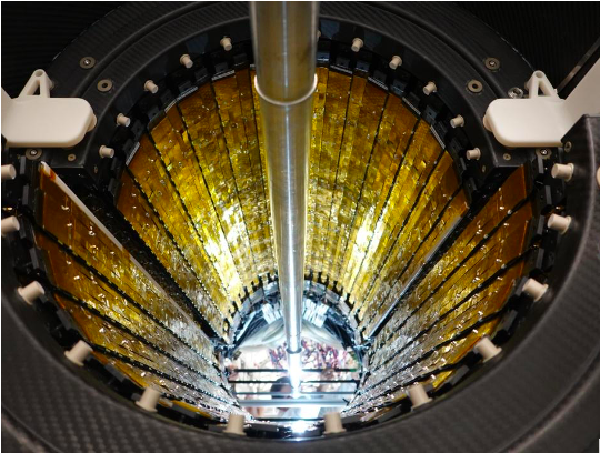
Fig 8: C side view of the ITS OB half barrel TOP being slid on the BOTTOM one, slowly reaching the final position. The insertion speed is of the order of 0.5mm/s.
Installation and verification
The installation of the four Half Barrels started on 15 March, when the OB Bottom half was placed on the truck in building 167 in Meyrin and moved to the site in Point 2. The OB Top half followed the path one week later and the mating of the two OB halves was completed by the end of March. The procedure went on very smoothly, according to the schedule. The following weeks were devoted to the connection of the services, power, data, and cooling systems, and then to the verification of the functionality of the detector components. The tests performed after installation showed that no damage occurred during the transport from Meyrin to Point 2. A detailed debugging campaign with 24 hours shifts
The IB installation required a more careful approach, given the very small clearance between layer 0 and the beam pipe. This is why the alignment of the different components was studied in building 167 with the aid of metrological surveys and multiple installation attempts on the cage replica. After almost a month of detailed studies, the IB bottom half was installed in the TPC on 7 May, and then mated with IB Top half on the late evening of 12 May. The delicate procedure required extra time, including a few late evening sessions, and repeated checks and surveys during the slow approach towards the final position (see fig. 9). Again, as in the case of the OB, tests were performed immediately after the mating to confirm that no significant damage occurred.
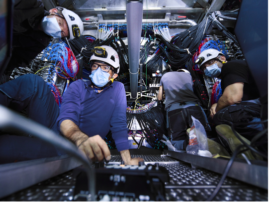
Fig. 9: The ITS mechanical experts checking the alignment of IB during the mating phase.
The ITS is now ready for starting standalone tests with cosmic rays, in view of joining the Muon Forward Tracker (MFT) for a common commissioning phase (Fig 10). The ALICE upgrade will be complete with the installation of the Fast Interaction Trigger (FIT), the next and the last step, foreseen for the next month. With the installation of the new ITS, ALICE achieves a fundamental milestone and looks forward to starting the data taking at the LHC. The excitation grows with the approaching of the beginning of RUN 3 in spring 2022. The next months foresee a global commissioning phase, starting in July, and the first tests with the LHC beam in October. A lot of work is ahead of us but the success of the upgraded detectors installation fills us with increasing confidence.
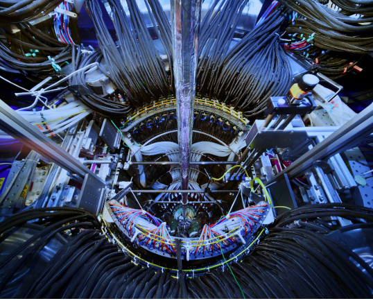
Fig 10: ITS installed and cabled, ready for data taking.