![]()
Installation of the second half of the LHCb SciFi detector
The installation of the first half of the LHCb SciFi detector was already discussed in a previous EP newsletter article.
The second half also proved to be rather challenging. First of all, the remaining six C-frames had to be assembled. Following CERN’s reopening and the gradual lifting of travel restrictions, the majority of the SciFi community returned safely to the laboratory, resulting in the speed up of the assembly. In general, the assembly of the SciFi C-frame was rather smooth and in time for the installation in the LHCb cavern. However, when it comes to such complex scientific tools such as particle detectors, it only takes one missing part to put the full assembly on hold. In the case of the SciFi detector, the installation of the front-end electronics proved rather challenging. Plenty of electronics had already been produced and assembled, however problems were detected in a fraction of them. Due to the extreme time pressure of getting the first six C-frames ready, the faulty front-end electronics were put aside for later repair. This means that for the last few C-frames only problematic electronics were available. They had to be thoroughly tested and the needed repairs made before installation; a process that turned out to be time consuming and clashing with the C-frame assembly schedule.
In this process, as pairs of C-frames became available, they were installed in the cavern. This was again done by inserting the C-frames into a transport cage and lowering it through the LHCb shaft. Each C-frame was then lifted onto the final rail as shown in Figure 3.
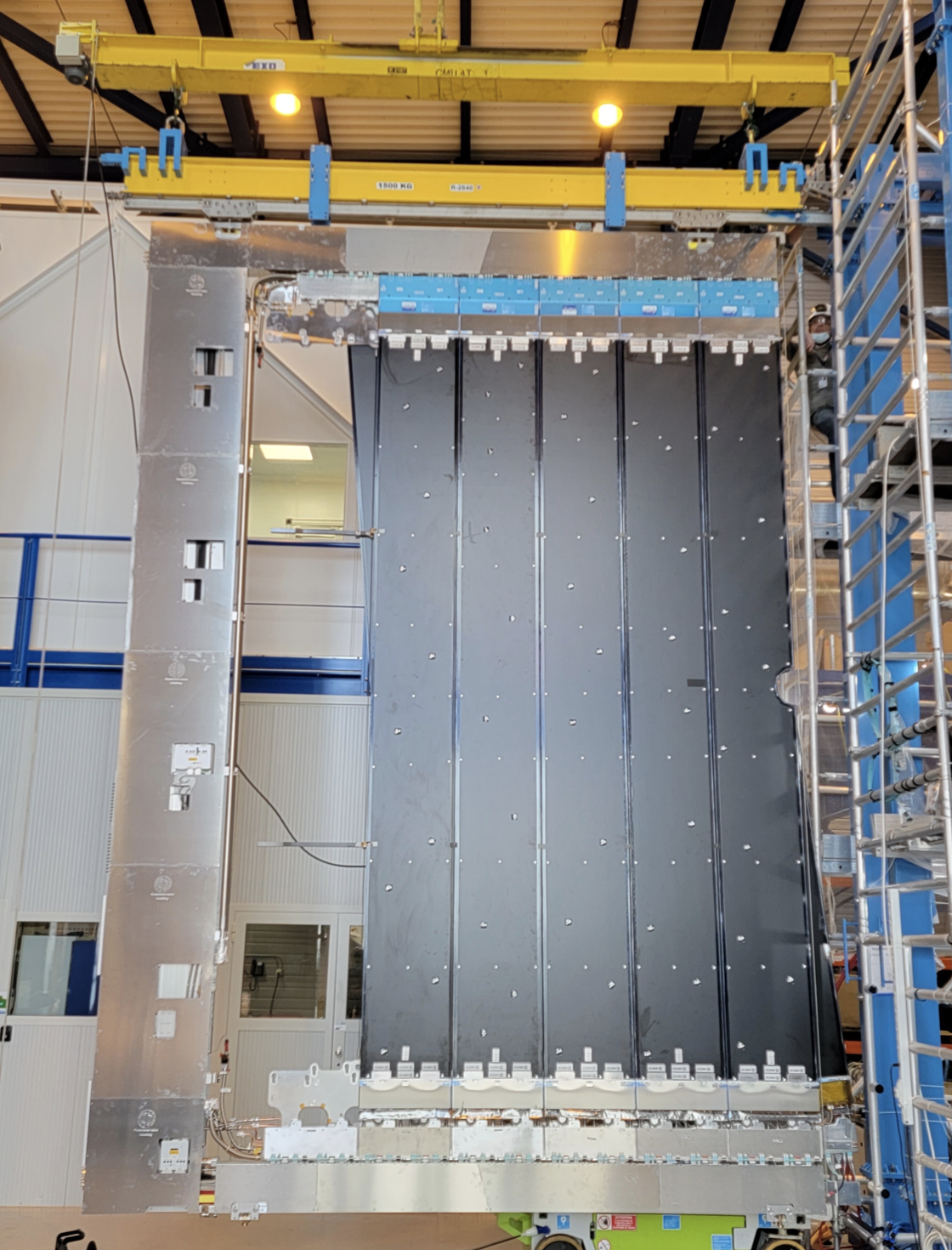
Figure 1. The C-frame with front-end electronics (blue) installed at the top, but not at the bottom. The cables and fibers for the bottom electronics is supported on dummy-front-end boxes.
While the C-frames where still being assembled, the preparation had already started in the LHCb cavern. The cables for the last six C-frames were filled into the moveable cable trays. Since there significantly less space contains compared to the first six C-frames, the cables could easily be filled with the cable trays laying on a platform as shown in Figure 2.
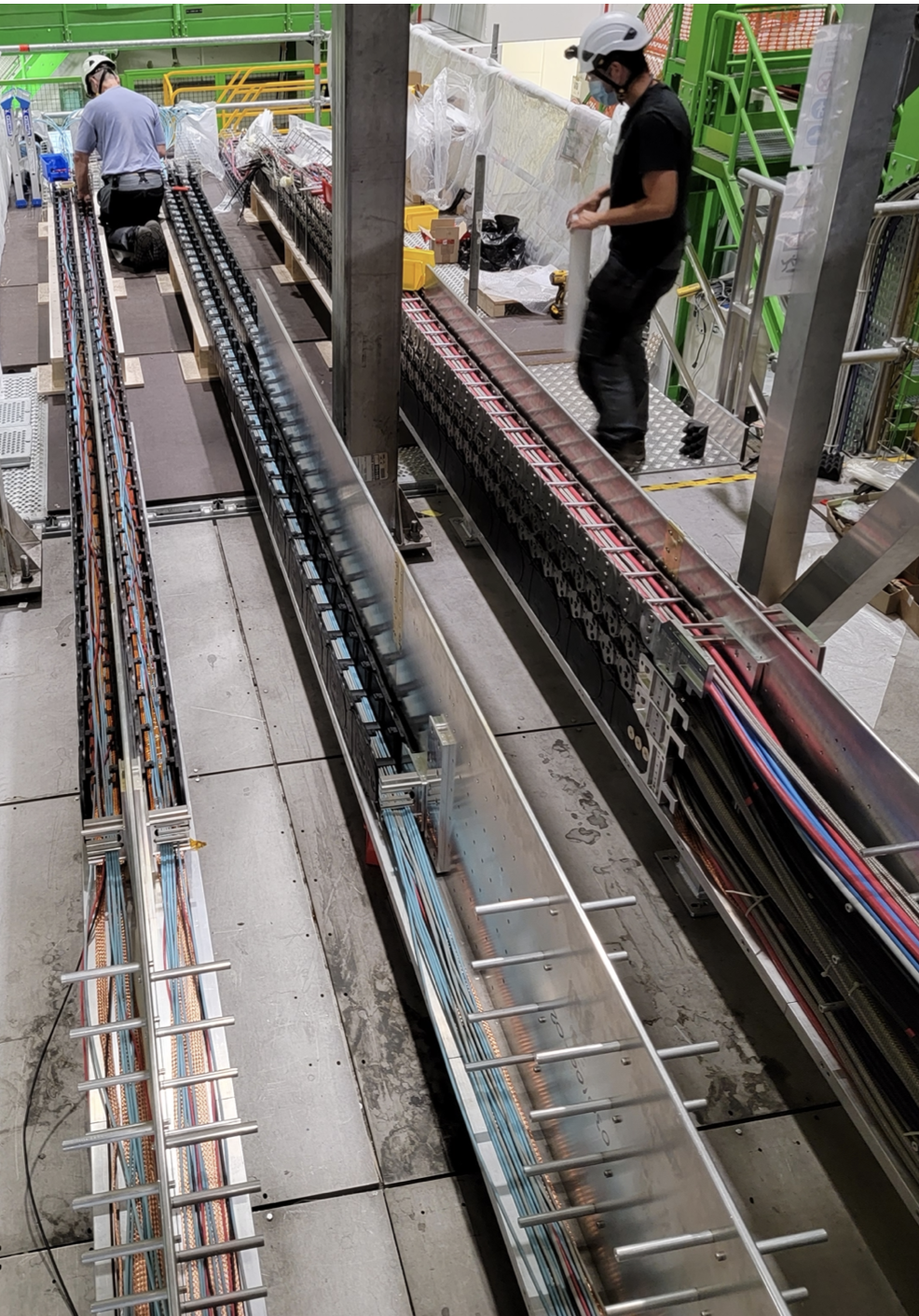
Figure 2. Cable trays being filled with cables.
In this process, as pairs of C-frames became available, they were installed in the cavern. This was again done by inserting the C-frames into a transport cage and lower it through the LHCb shaft. Each C-frame was then lifted onto the final rail as shown in Figure 3.
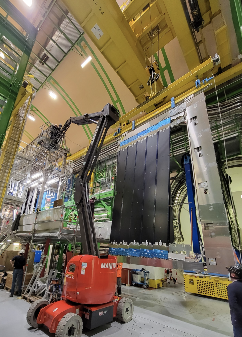
Figure 3. C-frames being moved from the transport cage onto the final rail.
Next followed the connection of the moveable cable trays to the C-frames as seen in Figure 4 and the connection of all cables and services inside the C-frame as seen in Figure 5.
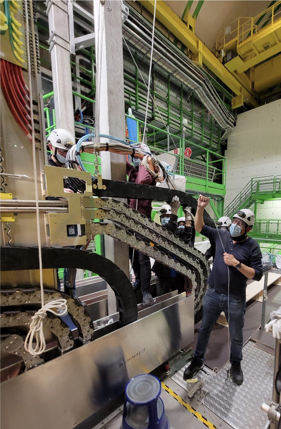
Figure 4. Connection of cable trays to C-frame.
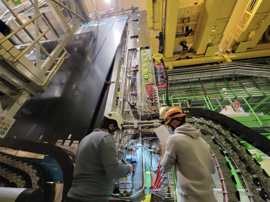
Figure 5. Connection of cable and services inside the C-frame.
After the last C-frame was installed, the repairs of the front-end electronics had progressed and it was ready for installation. The C-frames were pulled into a service position to provide access to the front-end electronics location. The installation of the front-end electronics was then made without any problems as shown in Figure 6.
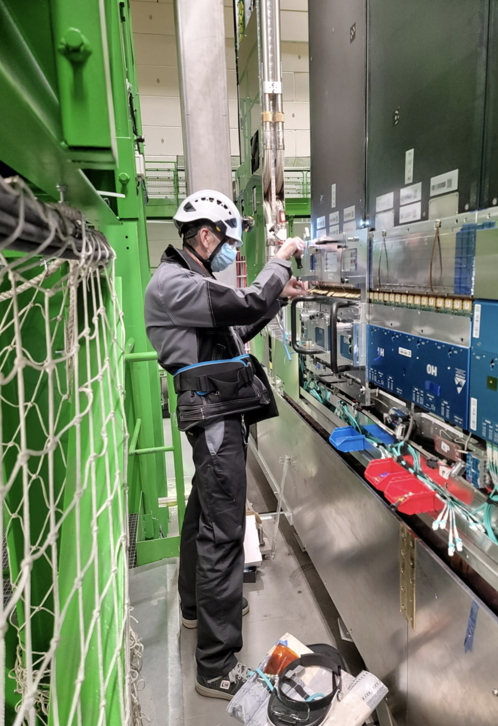
Figure 6. Installation of the last front-end electronics in the LHCb cavern.
All the C-frames were then aligned using laser survey. The main point of the alignment was to make sure that the beam-pipe cut-out is well fitted to the beam pipe, to make sure that the C-frames from each side of the beam pipe could overlap without touching (there is only a 2 mm clearance) and to provide a starting point for the later track-based alignment. The aligned C-frames are shown in Figure 7.
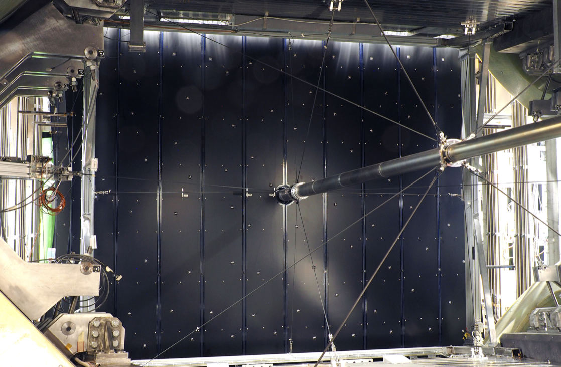
Figure 7. C-frames aligned and fully closed around the beam pipe (see from the magnet side).
To monitor the C-frames position over time, a camera system called BCAM was installed under the C-frames. The system laser-illuminates high refractive index glass balls, installed on the C-frames and photograph them with cameras from several angles. The system is shown in Figure 8.
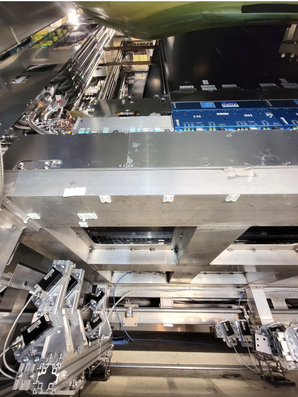
Figure 8. Cameras installed under the C-frames to monitor the C-frames position over time.
All the services for the second half of the detector have been commissioned. The cooling for the Silicon PhotoMultipliers (SiPMs) has been tested and they are now routinely operated at a setpoint of -50 °C, which gives a SiPM temperature better than the requirement of -40 °C.
Since the SciFi detector was preassembled and largely also pretested on the surface, the commissioning could start shortly after the C-frames were installed and connected. Communication has been established to all front-end electronics and the first performance data is being taking. The commissioning will continue to make the full detector operational.
All the C-frames of the second half of the detector is shown “maintenance position” in Figure 9. Thanks to the copious efforts of the community, the full SciFi detector has been successfully installed and is becoming ready to take data during the upcoming Run3 of the LHC.
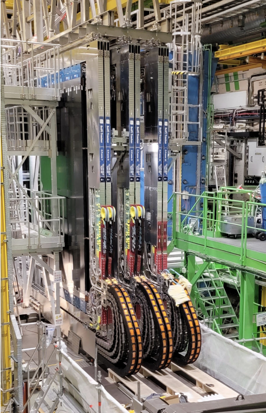
Figure 9. Six C-frame moved out to “maintenance position”. The 2 C-frames to the right still need to get optical fibers connected in this photo.